
PrinciplesOfOperation
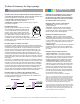

20
Technical Summary for Aspen pumps
Minipumps are not designed to run dry as they are
both cooled and lubricated by the water owing
through them. They require a oat switch to detect
the presence of water in the drain pan and activate
the pump only when water is present.
Minipumps always consists of two elements:
1. Pump body - Includes an electronic PCB
and the pump motor.
2. Reservoir - Contains the lter and the switching
mechanism to activate the pump. This must always
be kept level and clean for proper operation of the oat
switch. The lter must be cleaned regularly.
Minipumps are available in two styles:
1. Split type - (Orange or Aqua series) are designed
with separate pump and reservoir. The 2 elements are
connected together with a length of 1/4” id vinyl tube and
a communication cable, both of which are usually around
6 feet long. On our orange series pumps, this may be
extended if required.
2. Monobloc type - (Lime or White series) are designed
with both the pump and reservoir as one integral unit,
sharing a common body. No connecting tubes or wires
are needed.
Minipumps have two cable connections:
1. Power supply cable - color coded for different
voltages. Conductors for 115 volt pumps are white,
black and green, and conductors for 230 volt and univolt
pumps are red, black and green, and these colors are
standard for all models which operate on line voltage.
2. Overow switch cable - designed to break the
communication wire between the condenser and the
evaporator in case the water level in the reservoir rises
to an unacceptable level. This cable has 3 conductors,
gray (common), purple (normally closed) and orange
(normally open, generally not used). This color coding
is identical for all pump models except the Mini White
which has gray and purple only. During overow condi-
tion, pump will continue to operate.
Connection of the overow switch is mandatory.
NOTE: The overow switch uses dry contacts rated 5 amperes
@ 230vac. Communication circuits are usually well below this
rating. If a higher rating is desired, an external relay may be
added. The pump must remain powered for the overow switch
to operate when required. Factory approved wiring diagrams for
most minisplts are available at www.airtecproducts.com
Some minisplits have communication wires which are sensitive.
They utilize proprietary operating protocols and may need to be
wired differently. In these cases, the overow switch must be
wired according to a specic wiring diagram dedicated to that
particular manufacturer and/or model series
Peristaltic pumps offer three major benets for minisplit applications.
1. The ability to run both wet and dry, enables intermittent operation with a
reservoir and oat switch or continuous with the evaporator.
2. The capability to pump contaminates washed from the
evaporator coil during condensate production.
3. A High level of suction enables remote mounting up to 40 feet
away from the evaporator.
Peristaltic pump design:
Peristaltic pumps operate by utilizing a rotor wheel
which is electrically turned at slow speed and has
2 or more roller wheels spaced at points along its
perimeter. These rollers compress a rubber tube,
pinching it closed at each roller location. As the rotor
turns, uid inside the tubing is forced to ow in the
same direction as the rotor. Before the pinch point
is released, another roller pinches the starting point, preventing any
backow of liquid. This ‘peristaltic’ action produces a high level of suction
but has limited volume.
Peristaltic pumps are available in two styles:
1. Mechanical – Utilizes a oat inside a reservoir which is mounted below
the drain pan within the evaporator enclosure and, like a mini pump, requires
a breather tube to prevent airlock. The pump assembly can be remotely
mounted up to 10 feet away and is connected to the reservoir with ¼” id
tubing as well as a communication cable. Condensate water entering the
reservoir raises the oat, sending a signal which starts the pump. The
mechanical type peristaltic pump includes the added benet of an overow
switch similar to the mini pumps, however, the pump comes with a 3 pin plug
only and the cable to connect the overow switch to the evaporator must be
eld supplied.
2. Universal – For installations where a reservoir is not practical or distant re-
mote mounting is required. This pump incorporates a twin lead sensor cable
with 2 tips, 1 red and 1 blue, each of which are clipped onto a refrigeration
component such as the hot liquid line and the cold gas line of the refrigera-
tion circuit. When a preset temperature differential is detected between the
2 tips the pump begins to operate and removes any condensate as it is
produced. When the temperature differential subsides the pump switches off.
This pump does not incorporate an overow switch for the evaporator.
Peristaltic pumps are available in 115 and 230 volt models:
Power and overow wiring (where applicable) should be connected in
accordance with standard mini pump wiring instructions as detailed in the
Pump Wiring Section on page 21.
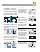
Mini/Maxi PumpsPeristaltic Pumps
INLET OUTLET
POWER
BLUE (COLD)
UNIVERSAL
RED (WARM)
FROM
DRAIN PAN
FROM
DRAIN PAN
MECHANICAL
POWER
OVERFLOW
Cable not provided
For more detailed selection information see our Technical Bulletin “Principles of Operation for Aspen Minipumps” on our web site.