
PrinciplesOfOperation

21
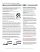
Correct pump wiring - Mini and Maxi models are
available in several different voltages. Power supply to
the pump should always be connected to the incom-
ing power terminal block on the evaporator (and not a
separate circuit) to ensure that the pump is powered
whenever the evaporator is powered. Some building
codes may require a separate circuit for a pump which
will overide our power wiring instructions. Building codes
may also require a disconnect switch for the evapora-
tor.The pump must be connected to the load terminals
to isolate both the pump and evaporator. (see diagram)
Effects of a dirty lter - Condensate cannot penetrate
the lter to activate pump or overow switch. Water will
back-up causing overow from the drain pan. All pump
models incorporate a lter in the reservoir which must
be cleaned regularly.
Breather tube function - For pump to operate
correctly, a breather tube is connected to the air intake
at the top of the reservoir to prevent airlock. The top of
the breather tube must be a minimum of 1” above the
top of the drain pan. All Mini pump models except the
Mini White require a breather tube, which must
remain unobstructed.
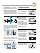
1. Pump is in Standby Mode:
Pump is off, oat rests on bottom of
reservoir, overow switch status is
normal so contacts across gray and
purple wires are closed and com-
munication wire from condenser to
evaporator remains energized.
2. Pump enters Operation Mode:
The evaporator condenses water
which ows into the drain pan and
through the drain hose into the
reservoir lifting the oat 3/4” activat-
ing the pump. The pump empties the
reservoir, lowering the oat, causing
the pump to switch off.
The pump returns to Standby Mode.
Overow switch status is normal,
so contacts across grey and purple
wires are closed and communication-
wire from condenser to evaporator-
remains energized. Cycle repeats
indenitely as long as water level
remains within normal limits.
3. Pump enters Alarm Mode:
The pump enters operation mode.
Water level continues to rise due to
pump failure, blockage or an under-
sized pump. The water level reaches
15/16”. The overow switch actuates
changing the status to abnormal. The
pump continues to run but contacts
across the gray and purple wire
open, breaking the communication
circuit to the evaporator, preventing
it from producing condensate, and
shutting down the system. When
occupant notices AC is not running,
they will contact a service tech to
investigate.
4. Pump reverts to Standby Mode:
Once reason for high water level has
been diagnosed and corrected, pump
reverts to standby mode.
Operating sequence of pump
FLOAT
MAGNET
WATER
LEVEL
3/4”
FLOAT
MAGNET
WATER
LEVEL
15/16”
WIRE TO
PUMP
FILTER
FLOAT
MAGNET
PUMP INTAKE
CONDENSATE
INLET
CONDENSATE
INLET
BREATHER
TUBE
WIRE TO
PUMP
FILTER
FLOAT
MAGNET
PUMP INTAKE
BREATHER
TUBE
1
2
3
4
FLOAT
MAGNET
WATER
LEVEL
3/4”
FLOAT
MAGNET
WATER
LEVEL
15/16”
WIRE TO
PUMP
FILTER
FLOAT
MAGNET
PUMP INTAKE
CONDENSATE
INLET
CONDENSATE
INLET
BREATHER
TUBE
WIRE TO
PUMP
FILTER
FLOAT
MAGNET
PUMP INTAKE
BREATHER
TUBE
1
2
3
4
FLOAT
MAGNET
WATER
LEVEL
3/4”
FLOAT
MAGNET
WATER
LEVEL
15/16”
WIRE TO
PUMP
FILTER
FLOAT
MAGNET
PUMP INTAKE
CONDENSATE
INLET
CONDENSATE
INLET
BREATHER
TUBE
WIRE TO
PUMP
FILTER
FLOAT
MAGNET
PUMP INTAKE
BREATHER
TUBE
1
2
3
4
FLOAT
MAGNET
WATER
LEVEL
3/4”
FLOAT
MAGNET
WATER
LEVEL
15/16”
WIRE TO
PUMP
FILTER
FLOAT
MAGNET
PUMP INTAKE
CONDENSATE
INLET
CONDENSATE
INLET
BREATHER
TUBE
WIRE TO
PUMP
FILTER
FLOAT
MAGNET
PUMP INTAKE
BREATHER
TUBE
1
2
3
4
WIRE TO
PUMP
FLOAT
MAGNET
PUMP INTAKE
CONDENSATE INLET
BREATHER
TUBE
BACKUP & OVERFLOW OF DRAIN PAN
WIRE TO
PUMP
PUMP INTAKE
CONDENSATE INLET
BREATHER
TUBE
1” MINIMUM
DRAIN PAN
FLOAT
MAGNET
FILTER
FILTER
WIRE TO
PUMP
FLOAT
MAGNET
PUMP INTAKE
CONDENSATE INLET
BREATHER
TUBE
BACKUP & OVERFLOW OF DRAIN PAN
WIRE TO
PUMP
PUMP INTAKE
CONDENSATE INLET
BREATHER
TUBE
1” MINIMUM
DRAIN PAN
FLOAT
MAGNET
FILTER
FILTER
PUMP
115V
115 VOLTS
EVAPORATOR
115V
GREEN
DISCONNECT
DO NOT WIRE PUMP
FROM INCOMING SIDE
OF DISCONNECT
BLACK
WHITE
G
L
N
NEUTRAL
LIVE
GROUND
PUMP
230V
230 VOLTS
EVAPORATOR
230V & UNIVOLT
GREEN
DISCONNECT
DO NOT WIRE PUMP
FROM INCOMING SIDE
OF DISCONNECT
BLACK
RED
G
L1
L2
LINE2
LINE1
GROUND
PURPLE GRAY
OVERFLOW SWITCH
PURPLE GRAY
OVERFLOW SWITCH
PURPLE GRAY
OVERFLOW SWITCH
PURPLE GRAY
OVERFLOW SWITCH