
Panasonic Mini-Split Wiring

Safe-t-Switch SS610e wiring Diagram
www.rectorseal.com
Wiring diagram for PANASONIC ductless minisplit system tted with
SS610E Electronic Overow Condensate Switch
Rev A - 10/2012
1. (Internal Installation) Place CPU inside evaporator enclosure or line set cover.
(External Installation) Mount CPU to a surface using double-sided tape or fasten using a screw.
2. Route lead wire into wiring space. Route Sensor into evaporator space. Do not cut Sensor wire. If necessary, remove bracket from Sensor before routing.
3. Sensor Mounting to Pan:
a. Attach Sensor to Pan Bracket.
b. Clip the Pan Bracket to where water level will be the highest in the evaporator condensate pan, press rmly in place.
c. Position the Wires up and Probe Pins down.
d. Adjust Sensor height by pushing the Sensor into the Pan Bracket. The Pan Bracket has a one-way ratchet mechanism. If the Sensor is set too low in the pan, push the Sensor from the lead side until it
disengages from the Pan Bracket, then reset. Adjust the sensor so that the Probe Pins are below the rim of the condensate pan. The switch will trip when water level reaches Probe Pins.
4. Sensor Mounting to Coil:
a. Attach Sensor to Coil Bracket. The Coil Bracket has 2 optional clips, one for regular 7mm coil and the other for 5mm coil. Choose clip size according to the actual coil tube diameter.
b. Clip the Coil Bracket onto evaporator coil. Insert the Bracket Clip between the ns or at the coil U-bend.
c. Position the Wires up and Probe Pins down.
d. Loosen Coil Bracket screws. Adjust Sensor height by moving Sensor to where water level will be the highest in the evaporator condensate pan. Adjust the Sensor so that the Probe Pins are below the
rim of the condensate pan. The switch will trip when water level reaches Probe Pins. Tighten Coil Bracket screws once adjustment is completed.
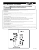
5. Wiring Option 1*: Interfering Communication Line
a. CONFIRM MAIN POWER SUPPLY IS SHUT OFF. Read air conditioner installation manual for the wiring terminal layout. Connect “Power Input” wires to indoor unit power supply terminal.
b. Cut the communication wire of the indoor unit. Connect “Common” and “NC” wires as shown in Figure 2. Insulate the exposed “NO” wire using insulating tape.
(WARNING: Electric shock hazard. Failure to insulate unused switch wires may cause personal injury and/or property damage.)
c. Use a wire nut when connecting wire to wire.
6. Wiring Option 2*: Interfering Power Line
a. CONFIRM MAIN POWER SUPPLY IS SHUT OFF. Read air conditioner installation manual for the wiring terminal layout. Connect “Power Input” wires to indoor unit power supply terminal.
b. Cut power wire of the indoor unit. Wire “Common” and “NC” wires as shown in Figure 3. Insulate the “NO” wire using insulating tape.
(WARNING: Electric shock hazard. Failure to insulate unused switch wires may cause personal injury and/or property damage.)
c. Use a wire nut when connecting wire to wire.
7. Wiring Option 3: Interfering Built-in Shut-o Terminal
a. CONFIRM MAIN POWER SUPPLY IS SHUT OFF.
b. Read air conditioner installation manual for the location and wiring of external shut-o terminal (or overow switch terminal). Wiring harness may be required to connect our switch to these terminals. If
the wiring harness doesn’t come with the air conditioner unit, please contact air conditioner manufacturer for assistance.
c. Read air conditioner installation manual to nd out the shut-o signal type. It is either Normally Closed or Normally Open. For Normally Closed, wire “Common” and “NC” wires to the shut-o terminal. For
Normally Opened, wire “Common” and “NO” wires to the shut-o terminal.
d. Use a wire nut when connecting wire to wire
* WIRING OPTION 1 AND 2 ILLUSTRATE WIRING TERMINAL OF A TYPICAL DUCTLESS MINI SPLIT SYSTEM. SYSTEMS FROM DIFFERENT MANUFACTURERS MAY BE WIRED DIFFERENTLY. PLEASE REFER TO AIR
CONDITIONER’S MANUALS FOR CORRECT WIRING TERMINAL LAYOUT AND WIRING INSTRUCTIONS.