52” CEILING FAN INSTALLATION AND OPERATION MANUAL Ceiling Fan Weight Including Accessories: 21.00 Lbs.
TABLE OF CONTENTS Tools and Materials Required.........................................................................................1 Package Contents ......................................................................................................... 1 Safety Rules................................................................................................................... 2 Mounting Options........................................................................................................
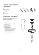
1. TOOLS AND MATERIALS REQUIRED Philips screwdriver Blade screwdriver 11 mm wrench Step ladder Wire cutters 2. PACKAGE CONTENTS Unpack your fan and check the contents. You should have the following items: b a a. b. c. d. Blade set (5) Hanger bracket Canopy 3” standard downrod assembly and 9” extra downrod e. Fan motor assembly f. Blade bracket set (5) g.
3. SAFETY RULES 1. To reduce the risk of electric shock, insure electricity has been turned off at the circuit breaker or fuse box before beginning. 8. To avoid personal injury or damage to the fan and other items, be cautious when working around or cleaning the fan. 2. All wiring must be in accordance with the National Electrical Code and local electrical codes. Electrical installation should be performed by a qualified licensed electrician. 9.
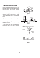
4. MOUNTING OPTIONS If there isn't an existing UL listed mounting box, then read the following instructions. Disconnect the power by removing fuses or turning off circuit breakers. Outlet box Secure the outlet box directly to the building structure. Use appropriate fasteners and building materials. The outlet box and its support must be able to fully support the moving weight of the fan 15.9 kgs (35lbs) or less. Do not use plastic outlet boxes.
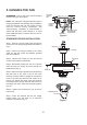
5. HANGING THE FAN REMEMBER to turn off the power. Follow the steps below to hang your fan properly. UL Listed electrial box NOTE: This ceiling fan is supplied with two types of hanging assemblies; the standard ceiling installation using the downrod with ball and socket mounting and the "close-to-ceiling" installation. The "close-to-ceiling" installation is recommended in rooms with less than 8-feet ceilings or in areas where additional space is desired from the floor to the fan blades.
CLOSE-TO-CEILING INSTALLATION 1. Remove the decorative canopy bottom cover from the canopy. (Fig. 8) Canopy 2. Pass the 120-volt supply wires through the center hole in the ceiling hanger bracket as shown in Fig. 5. Canopy bottom cover Figure 8 3. Secure the hanger bracket to the ceiling outlet box with the screws and washers provided with your outlet box. Screw and Lockwasher (3 of 6 places) 4. Remove three of the six screws and lock washers (every other one) from the collar of top motor. (Fig.
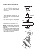
CHANGING THE DOWNROD (Optional) NOTE: Your fan comes with a 3" downrod attached to the hanger ball. In addition, a 9" downrod has been provided to be used in case the ceiling is higher, Perform the following steps for correct installation: Cross pin Hanger ball Set screw 1. Remove the hanger ball from downrod by loosening the setscrew at the top of the downrod which holds the hanger ball to the downrod. (Fig. 11) Downrod 2. Slide the hanger ball down the downrod and remove the support pin. 3.
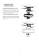
7. FINISHING THE INSTALLATION Outlet box Screws Hanger bracket STANDARD CEILING INSTALLATION Slide canopy up to the ceiling as shown in Figure 13. Make sure you place the wires safely into the outlet box. Secure the canopy to the hanger bracket with the four screws with your fan. Canopy CLOSE-TO-CEILING INSTALLATION Remove the fan from the hook on the hanger bracket. Secure the canopy to the hanger bracket as shown in Figure 14 with four screws included with your fan.
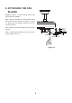
8. ATTACHING THE FAN BLADES Caution: Remove 5 rubber packing mounts and discard before installation. Step 1 Attach the blade to the blade bracket using the screws and fiber washers as shown in Figure 15. Start screw into bracket. Repeat for the two remaining screws. Step 2 Tighten each screw. Make sure the blade is straight. Screws Fiber washers Step 3 Fasten blade assembly to motor using the screws supplied. (Fig.
9. ATTACHING THE LIGHT KIT (Optional) Nut Lock washer Switch housing cover Plug 1. Remove the switch housing cover from the switch housing. Remove the plug from the switch housing cover, attach the light kit to the switch housing cover by feeding the light kit wires (black and white) through the hole of switch housing cover and then screw it onto the switch housing cover by nut & lock washer provided. Be sure it is tight enough to prevent light kit from vibrating loose. (Fig. 16) Light kit 2.
10. OPERATING YOUR FAN Turn on the power and check the operation of your fan. The pull chain controls the fan speed as follows: 1. 3-speed pull chain- it controls the fan speed as follows: 1 pull- High, 2 pulls- Medium, 3 pullsLow, and 4 pulls- Off. Speed settings for warm or cool weather depend on factors such as the room size, ceiling height, number of fans, and so on. The slide switch controls directions: forward (switch down) or reverse (switch up).
11. CARE OF YOUR FAN Here are some suggestions to help you maintain your fan 1. Because of the fan's natural movement, some connections may become loose. Check the support connections, brackets, and blade attachments twice a year. Make sure they are secure. (It is not necessary to remove fan from ceiling.) 2. Clean your fan periodically to help maintain its new appearance over the years. Use only a soft brush or lint-free cloth to avoid scratching the finish.
LIMITED LIFETIME WARRANTY