
Installation & Assembly

CAUTION – RISK OF SHOCK –
Disconnect Power at the main circuit breaker panel or main fuse
box before starting and during the installation.
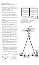
1) Take one loose arm, slip hook at end of arm through loop on
fixture body.
2) Pass threaded pipe on top of arm through hole in top trim.
3) Slip lockwasher over end of threaded pipe protruding from
inside top trim. Thread hexnut onto threaded pipe. Tighten
hexnut to secure arm in place.
4) Repeat steps 1-4 for remaining loose arm.
5) Take arm with fixture wire, pass fixture wire from top of arm
through hole in top trim.
6) Pass fixture wire through hole in lockwasher. Thread
lockwasher onto end arm protruding from inside top trim.
Pass fixture wire through hole in hexnut. Thread henxut
onto end of arm. Tighten hexnut to secure arm in place.
7) Pass fixture wire through hole in top plate. Lower top trim
down. Pass threaded pipe in center of top trim through hole
in top plate.
8) Pass fixture wire through hole in coupling. Thread coupling
onto threaded pipe protruding from top plate.
9) Pass fixture wire through end of stem. Thread end of stem into
coupling.
NOTE: Thread locking compound must be applied to all
stem threads to prevent accidental rotation of fixture during
cleaning, relamping, etc.
10) Pass fixture wire through remaining stems and screw stems
together.
11) Thread small threaded pipe into end of small loop.
12) Pass fixture wire through end of threaded pipe on small
loop. Thread small loop onto end of last stem.
13) Take threaded pipe from parts bag and screw in screw
collar loop a minimum of 6 mm (1/4”). Lock into place with
hexnut.
14) Run another hexnut down threaded pipe almost touching
first hexnut. Now screw threaded pipe into mounting strap.
Mounting strap must be positioned with extruded thread
faced into outlet box. Threaded pipe must protrude out the
back of mounting strap. Screw third hexnut onto end of
threaded pipe protruding from back of mounting strap.
15) Connect mounting strap to outlet box.
16) Unscrew the threaded ring from screw collar loop. Take
canopy and pass over screw collar loop. Approximately one
half of the screw collar loop exterior threads should be
exposed. Adjust screw collar loop by turning assembly up
or down in mounting strap. Remove canopy.
17) After desired position is found, tighten both top and bottom
hexnuts up against the bottom and top of the mounting
strap.
18) Slip canopy over screw collar loop and thread on threaded ring.
Attach chain (with fixture connected) to bottom of
screw collar loop. Unscrew threaded ring, let canopy and
threaded ring slip down.
19) Weave electrical wire and ground wire through chain links no
more than 3 inches apart. Pass wire through threaded ring,
canopy, screw collar loop, threaded pipe and into
outlet box.
20) Grounding instructions: (See Illus. A or B).
A) On fixtures where mounting strap is provided with a
hole and two raised dimples. Wrap ground wire from
outlet box around green ground screw, and thread into
hole.
B) On fixtures where a cupped washer is provided. Attach
ground wire from outlet box under cupped washer and
green ground screw, and thread into mounting strap.
If fixture is provided with ground wire. Connect fixture
ground wire to outlet box ground wire with wire connector
(not provided.) after following the above steps. Never
connect ground wire to black or white power supply wires.
21) Make wire connections (connectors not provided). Reference
chart below for correct connections and wire accordingly.
22) Raise canopy to ceiling.
23) Secure canopy in place by tightening threaded ring onto
screw collar loop.
24) Insert recommended bulbs (Not supplied).
25) Place glass trim into center of glass.
26) Lower glass down over socket. Pass hole in glass over
socket.
GREEN GROUND
SCREW
CUPPED
WASHER
OUTLET BOX
GROUND
FIXTURE
GROUND
DIMPLES
WIRE CONNECTOR
OUTLET BOX
GROUND
GREEN GROUND
SCREW
FIXTURE
GROUND
A
B
Connect Black or
Red Supply Wire to:
Connect
White Supply Wire to:
Black White
*Parallel cord (round & smooth)
*Parallel cord (square & ridged)
Clear, Brown, Gold or Black
without tracer
Clear, Brown, Gold or Black
with tracer
Insulated wire (other than green)
with copper conductor
Insulated wire (other than green)
with silver conductor
*Note: When parallel wires (SPT I & SPT II)
are used. The neutral wire is square shaped
or ridged and the other wire will be round in
shape or smooth (see illus.)
Neutral Wire
MOUNTING
BRACKET
GROUND WIRE
BALL
MOUNTING STRAP
STRAP
MOUNTING SCREWS
CANOPY
(2)LOCKWASHERS
(2)LOCK-UP KNOBS
TUBE
GLASS
TRIM PACK
GLASS
SOCKET
SOCKET CUP FINISH
MATCH FIXTURE BODY