TM-229 409A 2006−12 Eff w/Serial Number LG250111A Processes Multiprocess Welding Description Arc Welding Power Source EXTREME 360 CC/CV Auto-Line File: MULTIPROCESS
TABLE OF CONTENTS SECTION 1 − SAFETY PRECAUTIONS FOR SERVICING . . . . . . . . . . . . . . . . . . . . . . . . . . . . . . . . . . . . . . . . . . 1-1. Symbol Usage . . . . . . . . . . . . . . . . . . . . . . . . . . . . . . . . . . . . . . . . . . . . . . . . . . . . . . . . . . . . . . . . . . . . . . . . 1-2. Servicing Hazards . . . . . . . . . . . . . . . . . . . . . . . . . . . . . . . . . . . . . . . . . . . . . . . . . . . . . . . . . . . . . . . . . . . . 1-3. California Proposition 65 Warnings . .
TABLE OF CONTENTS 6-27. Power Interconnect Board PC2 Testing Information (Use with Section 6-28) . . . . . . . . . . . . . . . . . . . . 6-28. Power Interconnect Board PC2 Test Point Values . . . . . . . . . . . . . . . . . . . . . . . . . . . . . . . . . . . . . . . . . . 6-29. Front Panel/Display Board PC3 Testing Information (Use with Section 6-30) . . . . . . . . . . . . . . . . . . . . 6-30. Front Panel/Display Board PC3 Test Point Values . . . . . . . . . . . . . . . . . . . . . . . . . . . . . . . .
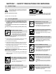
SECTION 1 − SAFETY PRECAUTIONS FOR SERVICING 1-1. Symbol Usage OM-229 409-B, safety_stm 8/03 Means Warning! Watch Out! There are possible hazards with this procedure! The possible hazards are shown in the adjoining symbols. Y Marks a special safety message. . Means “Note”; not safety related. This group of symbols means Warning! Watch Out! possible ELECTRIC SHOCK, MOVING PARTS, and HOT PARTS hazards. Consult symbols and related instructions below for necessary actions to avoid the hazards. 1-2.
MOVING PARTS can cause injury. D Keep away from moving parts. D Keep away from pinch points such as drive rolls. MAGNETIC FIELDS can affect pacemakers. D Pacemaker wearers keep away from servicing areas until consulting your doctor. OVERUSE can cause OVERHEATING. D Allow cooling period; follow rated duty cycle. D Reduce current or reduce duty cycle before starting to weld again. D Do not block or filter airflow to unit. H.F. RADIATION can cause interference. D High-frequency (H.F.
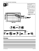
SECTION 2 − INTRODUCTION 2-1. Specifications Input Power Rated Output 3-Phase 350 A at 34 VDC, 60% Duty Cycle 1-Phase 300 A at 32 VDC, 60% Duty Cycle* Voltage Range in CV Mode Amperage Range in CC Mode Max. OpenCircuit Voltage 10−38 V 5−425 A 75 VDC RMS Amps Input at Rated Load Output, 60 Hz 3-Phase at NEMA Load Voltages and Class I Rating 208 V 230 V 400 V 460 V 575 V KVA KW 40.4 36.1 20.6 17.8 14.1 14.2 13.6 60.8 54.6 29.7 25.4 19.9 11.7 11.
2-3. Duty Cycle And Overheating Duty Cycle is percentage of 10 minutes that unit can weld at rated load without overheating. If unit overheats, output stops, a Help message is displayed and cooling fan runs. Wait fifteen minutes for unit to cool. Reduce amperage or voltage, or duty cycle before welding. . Single Phase Operation: The unit is supplied with a 8 AWG power cord. The rated output with 8 AWG is 300 amps, 32 volts at 40% duty cycle. To achieve 60% duty cycle change cord to 6 AWG.
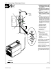
SECTION 3 − INSTALLATION 3-1. Selecting a Location 24 in (610 mm) Dimensions And Weight 80 lb (36.3 kg) 17 in (432 mm) 12-1/2 in (318 mm) 1 Movement 1 Y Do not move or operate unit where it could tip. 1 Lifting Handles Use handles to lift unit. 2 Hand Cart Use cart or similar device to move unit. 3 Rating Information Use rating information on rear panel to determine input power needs. 4 Line Disconnect Device Locate unit near correct input power supply.
3-2. Connecting 1-Phase Input Power Y Installation must meet all National and Local Codes − have only qualified persons make this installation. Y Disconnect and lockout/tagout input power before connecting input conductors from unit. 1 8 Y Always connect green or green/yellow conductor to supply grounding terminal first, and never to a line terminal. =GND/PE Earth Ground . The Auto-Line circuitry in this unit 10 automatically adapts the power source to the primary voltage being applied.
3-3. Connecting 3-Phase Input Power Y Installation must meet all National and Local Codes − have only qualified persons make this installation. Y Disconnect and lockout/tagout input power before connecting input conductors from unit. 3 = GND/PE Earth Ground 4 Y Always connect green or green/ yellow conductor to supply grounding terminal first, and never to a line terminal. . The Auto-Line circuitry in this unit au- tomatically adapts the power source to the primary voltage being applied.
3-4. Electrical Service Guide Y CAUTION: INCORRECT INPUT POWER can damage this welding power source. Phase to ground voltage shall not exceed +10% of rated input voltage. NOTE Actual input voltage should not be 10% less than minimum and/or 10% more than maximum input voltages listed in table. If actual input voltage is outside this range, output may not be available. Single-Phase Input Voltage 208 230 400 460 575 Input Amperes At Rated Output 60.8 54.6 29.7 25.4 19.
3-5.
‘ 3-7. Optional Gas Valve Operation And Shielding Gas Connection Obtain gas cylinder and chain to running gear, wall, or other stationary support so cylinder cannot fall and break off valve. 4 1 Cylinder 2 Regulator/Flowmeter Install so face is vertical. 3 GAS IN Gas Hose Connection Fitting has 5/8-18 right-hand threads. Obtain and install gas hose. 2 4 Gas In Fitting 5 Gas Out Fitting The Gas In and Gas Out fittings have 5/8-18 right-hand threads.
SECTION 4 − OPERATION 4-1. Front Panel Controls 1 Power Switch . The fan motor is thermostatically controlled and only runs when cooling is needed. 2 Voltmeter 3 Ammeter 4 V/A (Voltage/Amperage) Adjustment Control 5 Mode Switch The Mode switch setting determines both the process and output On/Off control (see Section 4-3). Source of control (panel or remote) for the amount of output is selected on the V/A Control switch. For Air Carbon Arc (CAC-A) cutting and goug- ing, place switch in Stick position.
4-2. Meter Functions NOTE The meters display the actual weld output values for approximately three seconds after the arc is broken. Mode Meter Reading At Idle V Scratch Start TIG Lift-Arc TIG Meter Reading While Welding 71.7 85 Preset Amps Actual Volts Actual Amps A V A 14.1 85 85 Preset Amps Actual Volts Actual Amps V A V A 10.3 85 Blank Preset Amps Actual Volts Actual Amps V A V A 24.5 250 Preset Volts Blank Actual Volts Actual Amps V A V A PPP PPP 24.
4-4. Lift-Arc TIG Procedure With Process Switch in the Lift-Arc TIG position, start an arc as follows: 1 “Touch” 1 TIG Electrode 2 Workpiece Touch tungsten electrode to workpiece at weld start point, hold electrode to workpiece for 1-2 seconds, and slowly lift electrode. An arc will form when electrode is lifted. 2 Normal open-circuit voltage is not present before tungsten electrode touches workpiece; only a low sensing voltage is present between electrode and workpiece.
SECTION 5 − THEORY OF OPERATION 5 4 Boost Input Inductor L1 Boost Snubber Inductor L2 7 2 1 Phase or 3 Phase Input Power Inverter Module Mod2 8 Input Pre-Regulator Module Mod1 1 6 9 Snubber Resistor Module RM1 Bus Capacitors C12, C13 3 Power Switch S1 10 Power Interconnect Board PC2 Current Transformer CT1 Bus Voltage Input Rectifier Voltage Input Boost Inductor Current Feedback Boost Gate Signal 20 Front Panel And Display Board PC3 21 21 Voltmeter V 22 Arc Control Ammeter A 23 Voltage/
Output Stabilizer L3 16 17 11 12 Series Capacitor C15 Work 18 Stick Boost Inductor L4 Stick Boost Relay CR1 Stick Boost Rectifier SR1 Output Diodes D1 & D2 Inverter Gating Signals 35 Fan Motor FM1 28 31 29 30 37 Secondary Heatsink Thermistor RT-1 Control/Auxiliary Power PC1 665 VAC Circuit Breaker CB1 34 115 VAC Electrode 38 Primary Heatsink Thermistor RT-2 34 VAC Center Tapped Control Transformer T2 33 Circuit Breaker CB2 36 ♦ Optional Gas Solenoid GS1 Positive (+) Weld Output
Theory Of Operation Components 1 Primary Input Power Single or Three-Phase AC primary power supply. 2 Power Switch S1 12 Main Transformer T1 Switching action of IGBTs in MOD2 creates the AC voltage source for T1 primary. T1 secondary outputs supply power to the weld circuit. Provides on/off control of primary input power to welding power source.
SECTION 6 − TROUBLESHOOTING 6-1. Checking Unit Before Applying Power . See Section 6-24 for test points and values and Section 9 for parts location. Y Discharge input capacitors according to Section 6-3 and be sure voltage is near zero before touching any parts. Y Before applying power to unit, complete the pre-power flowchart in Section 6-2 to avoid causing further damage.
PRE-POWER CHECKS 6-2. Pre-Power Flowchart Complete Section 6-3, Measuring Input Capacitor Voltage. Complete Sections 6-4 Thru 6-7 For Modules MOD1 And MOD2. All Measurements Pass? Complete Sections 6-13 Thru 6-18, Control/Auxiliary Board PC1. NO YES Complete Section 6-8 For Power Switch S1. All Measurements Pass? NO Replace PC1. YES All Measurements Pass? NO Replace S1. Complete Sections 6-19 and 6-20, Power Interconnect PC2. YES NO Complete Sections 6-9 and 6-10, Output Diodes D1 & D2.
PRE-POWER CHECKS 6-3. Measuring Input Capacitor Voltage Y Turn Off welding power source, and disconnect input power. Remove cover 5 Power Interconnect Board PC2 2 Voltmeter 3 Capacitor C12 Measure the dc voltage across C12 (+) Positive Terminal and C12 (−) Negative Terminal on PC2 as shown until voltage drops to near 0 (zero) volts. Typical Bleeder Resistor 25 to 1000 ohm, 5 watt resistor 1 Y Significant DC voltage can remain on capacitors after unit is Off.
PRE-POWER CHECKS 6-4. Input Pre-Regulator Module (MOD1) Test Equipment Needed: Y Read and follow safety information in Section 6-1 before proceeding. Y Wear an earth grounded wrist strap when performing pre-power checks. Remove wrist strap before performing any checks or procedures with power applied to the machine. 1 . Board layout may differ from that shown. 1 MOD1 Visually inspect MOD1 for damage.
PRE-POWER CHECKS 6-6. Inverter Module (MOD2) Y Read and follow safety information in Section 6-1 before proceeding. Test Equipment Needed: Y Wear an earth grounded wrist strap when performing pre-power checks. Remove wrist strap before performing any checks or procedures with power applied to the machine. 1 . Board layout may differ from that shown. 1 MOD2 Visually inspect MOD2 for damage.
PRE-POWER CHECKS 6-8. Power Switch (S1) Y Read and follow safety information in Section 6-1 before proceeding. 1 1 Power Switch S1 Visually inspect S1 for damage. Check switch mechanical operation by turning switch On and Off several times. Switch should snap sharply between the On and Off positions. Electrical Schematic Check switch electrical operation by checking continuity across S1 contacts with switch in the On position. With switch in the Off position, ohmmeter should read open.
PRE-POWER CHECKS 6-9. Output Diodes D1, D2 Y Read and follow safety information in Section 6-1 before proceeding. 1 2 Diode D1 Diode D2 Visually inspect D1 and D2 for damage. Check all measurements for output diodes D1 and D2 (see Section 6-10). + Weld Output Receptacles If all measurements passed, the output diodes D1 and D2 are OK. Continue to the end of the pre−power flowchart (see Section 6-2). − Test Equipment Needed: 2 1 Diodes D1, D2 Ref. 907 161 6-10.
PRE-POWER CHECKS 6-11. Stick Boost Rectifier (SR1) Y Read and follow safety information in Section 6-1 before proceeding. 1 Stick Boost Rectifier SR1 Visually inspect SR1 for damage. Check all measurements for stick boost rectifier SR1 (see Section 6-12). If all measurements passed, SR1 is OK. Continue to the end of the pre− power flowchart (see Section 6-2). 1 3 4 2 1 Test Equipment Needed: Ref. 907 161 6-12.
PRE-POWER CHECKS Notes OHM’S LAW VOLTAGE = CURRENT X RESISTANCE CURRENT = VOLTAGE RESISTANCE RESISTANCE = VOLTAGE CURRENT Extreme 360 TM-229 409 Page 25
PRE-POWER CHECKS 6-13. Control/Auxiliary Power Board PC1 − Auxiliary Power Circuit 5 1 8 11 6 7 4 13 12 9 10 2 3 1 8 2 7 3 6 4 5 Test Equipment Needed: . Pin sequence of IC chips. Ref. 217 184-F / 907 161 Y Read and follow safety information in Section 6-1 before proceeding. Y Wear an earth grounded wrist strap when performing pre-power checks. Remove wrist strap before performing any checks or procedures with power applied to the machine. .
PRE-POWER CHECKS 6-14. Control/Auxiliary Power Board PC1 − Auxiliary Power Circuit Test Point Values 60Hz Auxiliary Power Bridge DVM Positive Lead DVM Negative Lead DVM Diode DVM Ohms Auxiliary Bridge IGBT RC5 Pin 3 RC2 Pin 1 0.20 - 0.90 N/A Auxiliary Bridge IGBT RC5 Pin 1 RC2 Pin 1 0.20 - 0.90 N/A Auxiliary Bridge IGBT RC3 Pin 6 (PRECOM) RC5 Pin 3 0.20 - 0.90 N/A Auxiliary Bridge IGBT RC3 Pin 6 (PRECOM) RC5 Pin 1 0.20 - 0.
PRE-POWER CHECKS 6-15. Control/Auxiliary Power Board PC1 − Pre-Regulator Control Circuit 1 7 4 10 11 12 5 8 9 14 13 6 2 3 1 8 2 7 3 6 4 5 Test Equipment Needed: . Pin sequence of IC chips. Ref. 217 184-F / 907 161 Y Read and follow safety information in Section 6-1 before proceeding. Y Wear an earth grounded wrist strap when performing pre-power checks. Remove wrist strap before performing any checks or procedures with power applied to the machine. .
PRE-POWER CHECKS 6-16. Control/Auxiliary Power Board PC1 − Pre-Regulator Control Circuit Test Point Values Pre-Regulator Control DVM Positive Lead DVM Negative Lead DVM Diode DVM Ohms Buck IGBT U6 Pin 3 RC2 Pin 1 0.20 - 0.90 N/A Buck Diode RC3 Pin 6 (PRECOM) U6 Pin 5 (BUCK-COM) 0.20 - 0.90 N/A Buck IGBT Gate Drive IC U6 U6 Pin 6 U6 Pin 7 (BUCK+15V) 0.20 - 0.90 N/A D18 D18 Anode D18 Cathode 0.20 - 0.90 N/A D41 D41 Anode D41 Cathode 0.20 - 0.90 N/A D46 D46 Anode D46 Cathode 0.
PRE-POWER CHECKS 6-17. Control/Auxiliary Power Board PC1 − Inverter Control Circuit 1 2 4 3 6 7 5 Test Equipment Needed: 1 8 2 7 3 6 4 5 . Pin sequence of IC chips. Ref. 217 184-F / 907 161 Y Read and follow safety information in Section 6-1 before proceeding. Y Wear an earth grounded wrist strap when performing pre-power checks. Remove wrist strap before performing any checks or procedures with power applied to the machine. 1 Control Board PC1 Visually inspect PC1 for damage.
PRE-POWER CHECKS 6-18. Control/Auxiliary Power Board PC1 − Inverter Control Circuit Test Point Values Inverter Control DVM Positive Lead DVM Negative Lead DVM Diode DVM Ohms Inverter IGBT Gate Drive IC U16 U16 Pin 5 RC9 Pin 4 (+15V) 0.20 - 0.90 N/A Inverter IGBT Gate Drive IC U16 U16 Pin 7 RC9 Pin 4 (+15V) 0.20 - 0.90 N/A Inverter IGBT Gate Drive IC U16 RC9 Pin 6 (GND) U16 Pin 5 0.20 - 0.90 N/A Inverter IGBT Gate Drive IC U16 RC9 Pin 6 (GND) U16 Pin 7 0.20 - 0.
PRE-POWER CHECKS 6-19. Power Interconnect Board (PC2) 1 Test Equipment Needed: 22 21 23 10 18 17 15 5 16 20 9 19 11 3 12 4 2 6 13 14 7 8 Ref. 907 161 / 225 065-A Y Read and follow safety information in Section 6-1 before proceeding. Y Wear an earth grounded wrist strap when performing pre-power checks. Remove wrist strap before performing any checks or procedures with power applied to the machine.
PRE-POWER CHECKS 6-20. Power Interconnect Board (PC2) Test Point Values Power Interconnect Board PC2 DVM Positive Lead DVM Negative Lead DVM Diode DVM Ohms Pre-Charge Resistor R14 R14 Bottom R14 Top N/A 200 SCR Gate Resistor R10 R10 Left R10 Right N/A 10 - 16.5 SCR Gate Resistor R11 R11 Left R11 Right N/A 10 - 16.5 SCR Gate Resistor R12 R12 Left R12 Right N/A 10 - 16.5 Pre-Charge Diode D5 AC3 R14 Top 0.20 - 0.90 N/A Pre-Charge Diode D6 AC2 R14 Top 0.20 - 0.
Always check unit before applying power (see Sections 6-1 thru 6-18). 6-21. Troubleshooting Table . See Section 6-24 for test points and values and Section 9 for parts location. . Use MILLER Testing Booklet (Part No. 150 853) when servicing this unit. Trouble No weld output; unit completely inoperative. Remedy Follow Pre-Power Flowchart, and replace any failed components (see Section 6-2). Place line disconnect switch in On position (see Section 3-2 or 3-3).
Always check unit before applying power (see Sections 6-1 thru 6-18). Trouble Erratic or improper weld output. Remedy Use proper size and type of weld cable (see Section 3-4). Clean and tighten all weld connections. Check for proper input and output connections. Replace electrode. If a remote accessory is connected to remote 14 receptacle RC50: Check all remote accessory connections (proper pin/socket alignment).
Always check unit before applying power (see Sections 6-1 thru 6-18). 6-22. Voltmeter/Ammeter Diagnostics 1 2 3 V A HE.L P−1 V A HE.L P−2 V A HE.L P−3 . All directions are in reference to the front of the unit. All circuitry referred to is located inside the unit. 1 Help 1 Display Indicates a malfunction in the primary power circuit caused by an overcurrent condition in the primary IGBT switching circuit. If this display is shown, complete the Pre-Power Flowchart in Section 6-2.
Always check unit before applying power (see Sections 6-1 thru 6-18). 6-23. Enabling Low Open Circuit Voltage Stick Mode (Optional) Y Disconnect and lockout/tagout input power before removing cover. Follow this procedure to modify the unit for low open circuit voltage (OCV) when Stick welding. OCV is reduced to about 15 volts dc. 1 1 2 2 Front Panel And Display Board PC3 Switch SW1 Remove wrapper. Place switch position 1 in the Closed position by pressing actuator toward board. Reinstall wrapper.
Always check unit before applying power (see Sections 6-1 thru 6-18). 6-24.
Always check unit before applying power (see Sections 6-1 thru 6-18). See Section 6-27 for PC2 information R1 R2 R7 R8 R4 V6 R9 V7 R6 V14 R3 R5 Approx.
Always check unit before applying power (see Sections 6-1 thru 6-18). 6-25. Control/Auxiliary Power Board PC1 Testing Information (Use with Section 6-26) 9 12 Y Warning this procedure requires the machine to be electrically live. Significant DC voltage can remain on capacitors after unit is Off. 5 1 Be sure plugs are secure before applying power. See Section 6-26 for specific values during testing.
Always check unit before applying power (see Sections 6-1 thru 6-18). 6-26. Control/Auxiliary Power Board PC1 Test Point Values a) Tolerance − ±10% unless specified PC1 Voltage Readings Receptacle RC1 RC2 Pin Type b) Reference − to circuit common (lead 42) unless noted Value Y Do not measure − high voltage present. Y High voltage present. Voltages on this receptacle can exceed 900 volts DC from chassis (GND).
Always check unit before applying power (see Sections 6-1 thru 6-18). Section 6-26.
Always check unit before applying power (see Sections 6-1 thru 6-18). Section 6-26.
Always check unit before applying power (see Sections 6-1 thru 6-18). 6-27. Power Interconnect Board PC2 Testing Information (Use with Section 6-28) Y Warning this procedure requires the machine to be electrically live. Significant DC voltage can remain on capacitors after unit is Off. Be sure plugs are secure before applying power. See Section 6-28 for specific values during testing.
Always check unit before applying power (see Sections 6-1 thru 6-18). 6-28. Power Interconnect Board PC2 Test Point Values a) Tolerance − ±10% unless specified PC2 Voltage Readings Receptacle RC1 RC2 Pin Type b) Reference − to circuit common (lead 42) unless noted Value Y Do not measure − high voltage present. Y High voltage present. Voltages on this receptacle can exceed 900 volts DC from chassis (GND).
Always check unit before applying power (see Sections 6-1 thru 6-18). Section 6-28. Power Interconnect Board PC2 Test Point Values (Continued) Y High voltage present. The following terminals are used to interconnect the main power circuit with the primary supply, and with power circuit components not soldered in the pcb. Voltages on this receptacle can exceed 900 volts DC from chassis (GND).
Always check unit before applying power (see Sections 6-1 thru 6-18). 6-29. Front Panel/Display Board PC3 Testing Information (Use with Section 6-30) 2 1 Y Warning this procedure requires the machine to be electrically live. Significant DC voltage can remain on capacitors after unit is Off. Be sure plugs are secure before applying power. See Section 6-30 for specific values during testing. 1 2 3 4 Process Control Board PC3 Receptacle RC1 Receptacle RC2 Receptacle RC51 3 4 Test Equipment Needed: Ref.
Always check unit before applying power (see Sections 6-1 thru 6-18). 6-30.
Always check unit before applying power (see Sections 6-1 thru 6-18). Section 6-30.
SECTION 7 − MAINTENANCE 7-1. Routine Maintenance . Maintain more often Y Disconnect power before maintaining. during severe conditions. 3 Months Repair Or Replace Cracked Cables Replace Damaged Or Unreadable Labels Replace Cracked Torch Body Repair Or Replace Cracked Cables And Cords Clean And Tighten Weld Connections 6 Months Blow Out Inside 7-2. Blowing Out Inside Of Unit Y Do not remove case when blowing out inside of unit. To blow out unit, direct airflow through front and back louvers as shown.
SECTION 8 − ELECTRICAL DIAGRAMS . The circuits in this manual can be used for troubleshooting, but there might be minor circuit differences from your machine. Use circuit inside machine case or contact distributor for more information. The following is a list of all diagrams for models covered by this manual.
Figure 8-1. Circuit for EXTREME 360 (208 − 575 Volt) Eff.
211 328-E Extreme 360 TM-229 409 Page 53
Figure 8-2. Wiring Diagram for EXTREME 360 (208 − 575 Volt) Eff.
220 922-B Extreme 360 TM-229 409 Page 55
Figure 8-3. Wiring Diagram for EXTREME 360 (208 − 575 Volt) Eff.
220 922-B Extreme 360 TM-229 409 Page 57
Notes Start Your Professional Welding Career Now! TM-229 409 Page 58 400 Trade Square East, Troy, Ohio 45373 1-800-332-9448 www.welding.
TM-229 409 2006−12 Eff w/Serial Number LG250111A Processes Multiprocess Welding Description Arc Welding Power Source EXTREME 360 CC/CV Auto-Line Eff w/LG250111A And Following For OM-229 409 Revisions A Thru B
TM-229 409 Page 60 74 4 3 1 5 69 73 72 67 70 71 2 6 7 66 9 65 64 10 63 68 62 75 8 77 13 11 12 62 58 76 14 57 61 78 16 18 15 56 54 59 21 53 60 17 51 22 19 52 20 23 50 24 55 MOD 1 48 49 25 28 39 77 46 MOD 2 38 26 29 30 32 37 44 42 43 41 40 31 49 45 17 47 35 34 36 SECTION 9 − PARTS LIST FOR LG250111A AND FOLLOWING Ref. 803 690-F Figure 9-1.
Item No. Dia. Mkgs. Eff w/LG250111A And Following Part No. Description Quantity Figure 9-1. Parts Assembly . . . 1 . . . . . . . . . . . . . . . 229 541 . . Wrapper (Includes Insulators and Safety Labels) . . . . . . . . . . . . . . . . . . . . . . . . . . . . . . . . . . . . . . . . 175 256 . . Insulator, Side Rh (Not Shown) . . . . . . . . . . . . . . . . . . . . . . . . . . . . . . . . . . . . . . . . . . . . . . . . . . . . . . . 178 551 . . Insulator, Side (Not Shown) . . . . . . . . . . . . . .
Eff w/LG250111A And Following Item No. Dia. Mkgs. Part No. Description Quantity Figure 9-1. Parts Assembly (Continued) . . . 44 . . . . . RT2 . . . . . 199 798 . . Thermistor, Ntc 30K Ohm @ 25 Deg C 18in Lead . . . . . . . . . . . . . . . . . . . . . 45 . . . . . PC2 . . . . . 225 442 . . Circuit Card Assy, Interconnect W/Label & Clips (Includes) . . . . . . . . . . . . . 46 . . . . . . . . . . . . . . . 126 026 . . . . Label, Warning Electric Shock Can Kill Significant . . . . . . . . . . . . . . . .
Notes MATERIAL THICKNESS REFERENCE CHART 24 Gauge (.025 in) 22 Gauge (.031 in) 20 Gauge (.037 in) 18 Gauge (.050 in) 16 Gauge (.063 in) 14 Gauge (.078 in) 1/8 in (.125 in) 3/16 in (.188 in) 1/4 in (.25 in) 5/16 in (.313 in) 3/8 in (.375 in) 1/2 in (.
Owner’s Record Please complete and retain with your personal records. Model Name Purchase Date Serial/Style Number (Date which equipment was delivered to original customer.) Distributor Address City State Contact the Delivering Carrier to: Zip File a claim for loss or damage during shipment. For assistance in filing or settling claims, contact your distributor and/or equipment manufacturer’s Transportation Department.