OM-229 409B Processes Multiprocess Welding Description Arc Welding Power Source EXTREME 360 CC/CV Auto-Line 2006−10
TABLE OF CONTENTS SECTION 1 − SAFETY PRECAUTIONS - READ BEFORE USING . . . . . . . . . . . . . . . . . . . . . . . . . . . . . . . . . . . 1-1. Symbol Usage . . . . . . . . . . . . . . . . . . . . . . . . . . . . . . . . . . . . . . . . . . . . . . . . . . . . . . . . . . . . . . . . . . . . . . . . 1-2. Arc Welding Hazards . . . . . . . . . . . . . . . . . . . . . . . . . . . . . . . . . . . . . . . . . . . . . . . . . . . . . . . . . . . . . . . . . . 1-3.
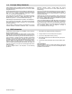
SECTION 1 − SAFETY PRECAUTIONS - READ BEFORE USING som _3/05 Y Warning: Protect yourself and others from injury — read and follow these precautions. 1-1. Symbol Usage Means Warning! Watch Out! There are possible hazards with this procedure! The possible hazards are shown in the adjoining symbols. Y Marks a special safety message. . Means “Note”; not safety related. This group of symbols means Warning! Watch Out! possible ELECTRIC SHOCK, MOVING PARTS, and HOT PARTS hazards.
ARC RAYS can burn eyes and skin. Arc rays from the welding process produce intense visible and invisible (ultraviolet and infrared) rays that can burn eyes and skin. Sparks fly off from the weld. D Wear an approved welding helmet fitted with a proper shade of filter lenses to protect your face and eyes when welding or watching (see ANSI Z49.1 and Z87.1 listed in Safety Standards). D Wear approved safety glasses with side shields under your helmet.
1-3. Additional Symbols For Installation, Operation, And Maintenance FIRE OR EXPLOSION hazard. MOVING PARTS can cause injury. D Do not install or place unit on, over, or near combustible surfaces. D Do not install unit near flammables. D Do not overload building wiring − be sure power supply system is properly sized, rated, and protected to handle this unit. D Keep away from moving parts such as fans. D Keep all doors, panels, covers, and guards closed and securely in place.
1-5. Principal Safety Standards Safety in Welding, Cutting, and Allied Processes, ANSI Standard Z49.1, from Global Engineering Documents (phone: 1-877-413-5184, website: www.global.ihs.com). Boulevard, Rexdale, Ontario, Canada M9W 1R3 (phone: 800−463−6727 or in Toronto 416−747−4044, website: www.csa−international.org). Recommended Safe Practices for the Preparation for Welding and Cutting of Containers and Piping, American Welding Society Standard AWS F4.
SECTION 2 − CONSIGNES DE SÉCURITÉ − LIRE AVANT UTILISATION som _3/05 Y Avertissement : se protéger et protéger les autres contre le risque de blessure — lire et respecter ces consignes. 2-1. Symboles utilisés Symbole graphique d’avertissement ! Attention ! Cette procédure comporte des risques possibles ! Les dangers éventuels sont représentés par les symboles graphiques joints. Y Indique un message de sécurité particulier . Signifie NOTE ; n’est pas relatif à la sécurité. 2-2.
LES RAYONS D’ARC peuvent entraîner des brûlures aux yeux et à la peau. Le rayonnement de l’arc du procédé de soudage génère des rayons visibles et invisibles intenses (ultraviolets et infrarouges) susceptibles de provoquer des brûlures dans les yeux et sur la peau. Des étincelles sont projetées pendant le soudage. D Porter un casque de soudage approuvé muni de verres filtrants approprié pour protéger visage et yeux pendant le soudage (voir ANSI Z49.1 et Z87.1 énuméré dans les normes de sécurité).
2-3. Dangers supplémentaires en relation avec l’installation, le fonctionnement et la maintenance Risque D’INCENDIE OU D’EXPLOSION. DES ORGANES MOBILES peuvent provoquer des blessures. D Ne pas placer l’appareil sur, au-dessus ou à proximité de surfaces inflammables. D Ne pas installer l’appareil à proximité de produits inflammables. D Ne pas surcharger l’installation électrique − s’assurer que l’alimentation est correctement dimensionnée et protégée avant de mettre l’appareil en service.
2-5. Principales normes de sécurité Safety in Welding, Cutting, and Allied Processes, ANSI Standard Z49.1, de Global Engineering Documents (téléphone : 1-877-413-5184, site Internet : www.global.ihs.com). Boulevard, Rexdale, Ontario, Canada M9W 1R3 (téléphone : 800-463-6727 ou à Toronto 416-747-4044, site Internet : www.csa-international.org). Recommended Safe Practices for the Preparation for Welding and Cutting of Containers and Piping, American Welding Society Standard AWS F4.
SECTION 3 − INTRODUCTION 3-1. Specifications Input Power Rated Output 3-Phase 350 A at 34 VDC, 60% Duty Cycle 1-Phase 300 A at 32 VDC, 60% Duty Cycle* Voltage Range in CV Mode Amperage Range in CC Mode Max. OpenCircuit Voltage 10−38 V 5−425 A 75 VDC RMS Amps Input at Rated Load Output, 60 Hz 3-Phase at NEMA Load Voltages and Class I Rating 208 V 230 V 400 V 460 V 575 V KVA KW 40.4 36.1 20.6 17.8 14.1 14.2 13.6 60.8 54.6 29.7 25.4 19.9 11.7 11.
3-3. Duty Cycle And Overheating Duty Cycle is percentage of 10 minutes that unit can weld at rated load without overheating. If unit overheats, output stops, a Help message is displayed and cooling fan runs. Wait fifteen minutes for unit to cool. Reduce amperage or voltage, or duty cycle before welding. . Single Phase Operation: The unit is supplied with a 8 AWG power cord. The rated output with 8 AWG is 300 amps, 32 volts at 40% duty cycle. To achieve 60% duty cycle change cord to 6 AWG.
SECTION 4 − INSTALLATION 4-1. Selecting a Location 24 in (610 mm) Dimensions And Weight 80 lb (36.3 kg) 17 in (432 mm) 12-1/2 in (318 mm) 1 Movement 1 Y Do not move or operate unit where it could tip. 1 Lifting Handles Use handles to lift unit. 2 Hand Cart Use cart or similar device to move unit. 3 Rating Information Use rating information on rear panel to determine input power needs. 4 Line Disconnect Device Locate unit near correct input power supply.
4-2. Connecting 1-Phase Input Power Y Installation must meet all National and Local Codes − have only qualified persons make this installation. Y Disconnect and lockout/tagout input power before connecting input conductors from unit. 1 8 Y Always connect green or green/yellow conductor to supply grounding terminal first, and never to a line terminal. =GND/PE Earth Ground . The Auto-Line circuitry in this unit 10 automatically adapts the power source to the primary voltage being applied.
4-3. Connecting 3-Phase Input Power Y Installation must meet all National and Local Codes − have only qualified persons make this installation. Y Disconnect and lockout/tagout input power before connecting input conductors from unit. 3 = GND/PE Earth Ground 4 Y Always connect green or green/ yellow conductor to supply grounding terminal first, and never to a line terminal. . The Auto-Line circuitry in this unit au- tomatically adapts the power source to the primary voltage being applied.
4-4. Electrical Service Guide Y CAUTION: INCORRECT INPUT POWER can damage this welding power source. Phase to ground voltage shall not exceed +10% of rated input voltage. NOTE Actual input voltage should not be 10% less than minimum and/or 10% more than maximum input voltages listed in table. If actual input voltage is outside this range, output may not be available. Single-Phase Input Voltage 208 230 400 460 575 Input Amperes At Rated Output 60.8 54.6 29.7 25.4 19.
4-5.
‘ 4-7. Optional Gas Valve Operation And Shielding Gas Connection Obtain gas cylinder and chain to running gear, wall, or other stationary support so cylinder cannot fall and break off valve. 4 1 Cylinder 2 Regulator/Flowmeter Install so face is vertical. 3 GAS IN Gas Hose Connection Fitting has 5/8-18 right-hand threads. Obtain and install gas hose. 2 4 Gas In Fitting 5 Gas Out Fitting The Gas In and Gas Out fittings have 5/8-18 right-hand threads.
SECTION 5 − OPERATION 5-1. Front Panel Controls 1 Power Switch . The fan motor is thermostatically controlled and only runs when cooling is needed. 2 Voltmeter 3 Ammeter 4 V/A (Voltage/Amperage) Adjustment Control 5 Mode Switch The Mode switch setting determines both the process and output On/Off control (see Section 5-3). Source of control (panel or remote) for the amount of output is selected on the V/A Control switch. For Air Carbon Arc (CAC-A) cutting and goug- ing, place switch in Stick position.
5-2. Meter Functions NOTE The meters display the actual weld output values for approximately three seconds after the arc is broken. Mode Meter Reading At Idle V Scratch Start TIG Lift-Arc TIG Meter Reading While Welding A 71.7 85 Preset Amps Actual Volts Actual Amps A V A 14.1 85 85 Preset Amps Actual Volts Actual Amps V A V A 10.3 85 Blank Preset Amps Actual Volts Actual Amps V A V A 24.5 250 Preset Volts Blank Actual Volts Actual Amps V A V A PPP PPP 24.
5-4. Lift-Arc TIG Procedure With Process Switch in the Lift-Arc TIG position, start an arc as follows: 1 “Touch” 1 TIG Electrode 2 Workpiece Touch tungsten electrode to workpiece at weld start point, hold electrode to workpiece for 1-2 seconds, and slowly lift electrode. An arc will form when electrode is lifted. 2 Normal open-circuit voltage is not present before tungsten electrode touches workpiece; only a low sensing voltage is present between electrode and workpiece.
SECTION 6 − MAINTENANCE & TROUBLESHOOTING 6-1. Routine Maintenance . Maintain more often Y Disconnect power before maintaining. during severe conditions. 3 Months Repair Or Replace Cracked Cables Replace Damaged Or Unreadable Labels Replace Cracked Torch Body Repair Or Replace Cracked Cables And Cords Clean And Tighten Weld Connections 6 Months Blow Out Inside 6-2. Blowing Out Inside Of Unit Y Do not remove case when blowing out inside of unit.
6-3. Voltmeter/Ammeter Help Displays 1 2 3 V A HE.L P−1 V A HE.L P−2 V A HE.L P−3 . All directions are in reference to the front of the unit. All circuitry referred to is located inside the unit. 1 Help 1 Display Indicates a malfunction in the primary power circuit. If this display is shown, contact a Factory Authorized Service Agent. 2 Help 2 Display Indicates a malfunction in the thermal protection circuitry. If this display is shown, contact a Factory Authorized Service Agent.
SECTION 7 − ELECTRICAL DIAGRAM Figure 7-1.
211 328-E OM-229 409 Page 23
OM-229 409 Page 24 74 4 3 1 5 69 Figure 8-1. Parts Assembly 73 72 67 70 71 2 6 7 66 9 65 64 10 63 68 62 75 8 77 13 11 12 62 58 76 14 57 61 78 16 18 15 56 54 59 21 53 60 17 51 22 19 52 20 23 50 24 55 MOD 1 48 49 25 28 39 77 46 MOD 2 38 26 29 30 32 37 44 42 43 41 40 31 49 45 17 47 35 34 36 SECTION 8 − PARTS LIST Ref.
Item No. Dia. Mkgs. Part No. Description Quantity Figure 8-1. Parts Assembly . . . 1 . . . . . . . . . . . . . . . 229 541 . . Wrapper (Includes Insulators and Safety Labels) . . . . . . . . . . . . . . . . . . . . . . . . . . . . . . . . . . . . . . . . 175 256 . . Insulator, Side Rh (Not Shown) . . . . . . . . . . . . . . . . . . . . . . . . . . . . . . . . . . . . . . . . . . . . . . . . . . . . . . . 178 551 . . Insulator, Side (Not Shown) . . . . . . . . . . . . . . . . . . . . . . . . . . . . . .
Item No. Dia. Mkgs. Part No. Description Quantity Figure 8-1. Parts Assembly (Continued) . . . 44 . . . . . RT2 . . . . . 199 798 . . Thermistor, Ntc 30K Ohm @ 25 Deg C 18in Lead . . . . . . . . . . . . . . . . . . . . . 45 . . . . . PC2 . . . . . 225 442 . . Circuit Card Assy, Interconnect W/Label & Clips (Includes) . . . . . . . . . . . . . 46 . . . . . . . . . . . . . . . 126 026 . . . . Label, Warning Electric Shock Can Kill Significant . . . . . . . . . . . . . . . . . . . . . . . . . . . . . . .
Warranty Effective January 1, 2006 (Equipment with a serial number preface of “LG” or newer) * This limited warranty supersedes all previous manufacturers warranties and is exclusive with no other guarantees or warranties expressed or implied. LIMITED WARRANTY − Subject to the terms and conditions below, warrants to its original retail purchaser that new equipment sold after the effective date of this limited warranty is free of defects in material and workmanship at the time it is shipped from factory.
Owner’s Record Please complete and retain with your personal records. Model Name Purchase Date Serial/Style Number (Date which equipment was delivered to original customer.) Distributor Address City State Contact the Delivering Carrier to: Zip File a claim for loss or damage during shipment. For assistance in filing or settling claims, contact your distributor and/or equipment manufacturer’s Transportation Department.