
Operation Guide

Copyright RED Digital Cinema Feb 07 2008
60
Appendix B: Power and Timecode I/O.
D.C Power Input
The power input connector accepts a DC voltage between +11.5 and +17V DC. When used
with a RED-BRICK 140 battery, the camera also receives battery status information. The power
input is protected against reverse-polarity connection, ESD, under voltage, and over current.
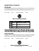
Mating connector LEMO FGG.2B.306.CLAD62Z (straight)
1
2
3
4
5
6
View into camera Power Input connector
Pin
Signal
Description
1
2
+VBATT
Power input, +11.5 to +17VDC
3
4
-VBATT
Power return
5
SCL_BATT
Battery pack I2C bus clock
6
SDA_BATT
Battery pack I2C bus bi-directional data
Note: It is very important that both of the +VBATT and –VBATT pins are wired
up. DO NOT fabricate any power cables with just one each of the +VBATT and
–VBATT pins wired up, as this can damage the camera power supply assembly.
Auxiliary Power Outputs
The camera provides two auxiliary power output connectors on its back panel. Each supplies
un-regulated +11.5 – +17V battery pass-through power. Maximum sustained current draw is 1
Amp per output. Outputs are over-current protected, and switched by camera firmware.
Mating connector LEMO FGG.0B.304.CLAD42Z (straight)
1
4
3
2
View into camera Auxiliary P ower Output connector