
Operation Guide


Copyright RED Digital Cinema Apr 30 2009
72
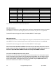
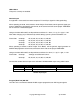
Pin:
Signal
Description
Direction
1
GND
Camera ground
--
2
RTX
RS232 Transmit Data
Out
3
+12V
Regulated 12V output, 500mA max.
Out
4
-
-- Reserved: do not connect -
-
5
SW2
“Record Clip” switch closure
In
6
-
-- Reserved: do not connect -
-
7
SW1
“Playback Clip” switch closure
In
8
RRX
RS232 Receive Data
In
9
-
-- Reserved: do not connect -
-
10
-
-- Reserved: do not connect -
-
Note: Pins 4, 6, 9 and 10 are reserved for future use.
RED-EVF Interface
The RED-EVF interface is a custom digital video and power interconnection between the camera
and a RED-EVF. Due to the data integrity nature of this interface, the pin-out is not published.
Contact RED technical support for details of available RED-EVF cable lengths.
RED-LCD Interface
The RED-LCD interface is a custom digital video and power interconnection between the camera
and a RED-LCD. Due to the data integrity nature of this interface, the pin-out is not published.
Contact RED technical support for details of available RED-EVF cable lengths.
Note: The Aux 232, RED-EVF and RED-LCD connectors use the same shell size. Do not at-
tempt to force fit a 10-pin Aux 232 cable into a 16-pin RED-EVF or RED-LCD connector, or
force fit a 16-pin RED-EVF or RED-LCD cable into a 10-pin Aux/RS232 connector.
Line Level and Microphone Level Audio Inputs
A three-pin mini-XLR connector is provided for each of the camera’s Line / Microphone inputs.
Audio is recorded at 24-bit 48KHz, which provides high audio fidelity and wide dynamic range.
The Line Level and Microphone Level analog audio input signals are routed via a high quality
A/D and pre-amplifier, whose gain stage may be controlled using the Input Level control to
achieve the desired audio reference / recording level.