THANKS Congratulations and thank you for your purchase of a RED ONE™ camera. Before unpacking and assembling the camera body and any accessories, please review the QUICK START GUIDE. If there is any physical damage to your camera or accessories, please contact us immediately at info@red.com. The following instructions will outline basic assembly of the RED ONE™ camera body, RED™ BASE PRODUCTION PACK, RED™ LCD, REDFLASH™, RED DRIVE®, RED BRICK®, and RED™ Lens.
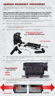
CAMERA ASSEMBLY PROCEDURE The following instructions will outline basic assembly of the RED ONE™ camera body, BASE PRODUCTION PACK, RED™ LCD, REDFLASH™, RED DRIVE®, and RED BRICK®. When connecting cables between camera and components, align Red dots on cable and connector and press in firmly to establish a secure connection. Wingnuts can be indexed by pulling out and rotating to desired position. This may be necessary during assembly to clear components. 1. 2.
7. Assemble universal mount, wing nuts and washers - do not tighten. 8. Slide universal mount over rods at rear of camera leaving approx. 1/2”3/4” of rods exposed at end. Lock in place using wing nuts. 9. UNIVERSAL MOUNT INSTALLED Extend attachment arm on cradle assembly and install base to universal mount using one (1) button-head Allen bolt (and two (2) Allen bolts, if desired). 10. Adjust and secure cradle assembly. CRADLE MOUNT INSTALLED ON UNIVERSAL MOUNT 5/8 X 16 BUTTON-HEAD CAP-SCREW 11.
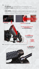
13. Install top handle (pointing toward rear of camera) using two (2) Allen bolts. TOP HANDLE INSTALLED 14. Assemble right handle, wing nuts and washers - do not tighten. 15. Slide right handle over front of either rod. Lock in place using wing nut. NOTE: POSITION HANDLE HORIZONTALLY FRONT OF CAMERA TO EASE IN ASSEMBLY RIGHT HANDLE INSTALLED 16. Working from front of camera, remove body cap from PL Mount by rotating retaining ring counter-clockwise. 17.
18. Install media. • SD MEMORY: Insert supplied SD Memory Card at left front of camera. • COMPACT FLASH: Insert REDFLASH™ compact flash (CF) card at left rear of camera. • RED DRIVE®: Loosen thumb screws on sides of cradle assembly, slide into v-blocks in cradle and tighten thumb screws. Connect 90˚ end of cable to RED DRIVE® and straight end to DRIVE connector on rear of camera.
20. Install LCD to long stud on arm and tighten thumb screw. Connect cable between LCD and MONITOR connector on side of camera body. ALWAYS ALIGN RED-DOTS TIGHTEN THUMB-SCREW TO SECURE LCD 21. Connect cable from cradle mount to POWER connector on rear of camera. ATTACH POWER CABLE TO CAMERA 22. Slide RED BRICK® battery into v-mount battery plate on Cradle Assembly. NOTE: To ensure a good connection between battery and RED Cradle V-plate adapter, it is recommended to perform a break-in sequence.
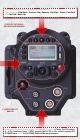
CAMERA CONTROLS This section describes the physical controls and connectors on the RED ONE™ camera. LEFT FRONT OF CAMERA On the left front of the camera body are a RECORD button (RED) to start and stop recording and two (2) User Buttons. User Button 1 is pre-assigned to AUTO WB (White balance) and User Button 2 is pre-assigned to 1:1 FOCUS CHECK, these button can be reprogrammed as desired.
Five buttons above the LCD display control clip playback. From left to right,Clip Start / Previous Clip, Reverse, Clip Play / Pause, Fast Fwd and Clip End / Next Clip. DISPLAY SHOWING: PIN, BUILD AND VERSION POWER ON/OFF SWITCH Underneath the status display buttons are (from left to right) the Power On/Off switch, 2 - 4-Pin Auxiliary Power / GPIO outputs (AUX 12V), 6-Pin camera system DC POWER input and a 16-Pin DRIVE External Memory interface.
CAMERA I/O CONNECTIONS The right side of the camera contains all the video, audio and time code inputs and outputs. • 1 - 3.5mm stereo headphone jack • 4 - DIN 1.0/2.
BACK FOCUS ADJUSTMENT 1. Level the camera on a stable surface or tripod. 2. Set a focus chart at a medium distance from the camera. (5 to 10 feet) 3. Attach a medium length prime lens to the camera, (50 to 75mm) and set the lens focus to match the appropriate distance the camera is away from the chart. 4. Using a 5/32” Allen wrench, loosen the two (2) screws on the focus ring near the front of the camera. FOCUS-RING SCREWS 5. Adjust the camera focus ring until the focus chart is in focus.
DISCLAIMER • RED™ has made every effort to provide clear and accurate information in this QUICK START GUIDE, which is provided solely for the user’s information. While thought to be accurate, the information in this document is provided strictly “as is” and RED™ will not be held responsible for issues arising from typographical errors or user’s interpretation of the language used herein that is different from that intended by RED™.