
Quick Start Guide


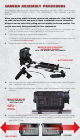


The right side of the camera contains all the video, audio and time code inputs and outputs.
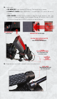
1. To power up the camera, press and release the Power On/Off switch.
• When using a RED BRICK® battery, press the power on/off switch once.
• When using a RED-CHARGER, connect it via the supplied power cable. Plug the
RED-CHARGER into an AC power source and switch it on. After the green LED
illuminates on the RED-CHARGER, the camera can be powered on by pressing
the On/Off switch.
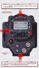
2.
The rear status display will illuminate and display “Booting” properties.
3. After approximately 60 seconds the display the camera PIN, rmware build and rm-
ware version will display.
• The PIN is a unique product identication number included in the metadata re-
corded with each image. The PIN provides RED with tracking data for customer
service and assistance in authenticating legal ownership of the camera.
4.
The rear display will automatically change to current camera values.
5. When the camera is ready for use, the lower LED to the right of the status display
turns green.
6.
To power down the camera, press and release the Power On/Off switch.
• 1 - 3.5mm stereo headphone jack
• 4 - DIN 1.0/2.3 video connectors; 2
upper that support Program HD-SDI,
2 lower that support PREVIEW HD-SDI
and Video GENLOCK
• 1 - HDMI output - to connect to external
monitors
• 1 - USB Master port - to connect the
camera to another camera, acting as
the master
• 1 - USB Slave port - to connect the
camera to another camera, acting as
the slave
• 1 - 5-pin mini-XLR AUDIO OUT
• 1 - 5-pin TIMECODE input/output
• 4 - 3-pin mini-XLR audio inputs (AUDIO
1, 2 and AUDIO 3-4).
• 1 - VIEWFINDER connector (RED EVF)
• 1 - MONITOR connector (RED LCD)
• 1 - 10-pin push lock LEMO connector
supporting the Aux/RS232 port that can
interface to a variety of B4 lenses and
lens motor control devices
CAMERA I/O CONNECTIONSCAMERA I/O CONNECTIONS
POWERING CAMERA ON/OFFPOWERING CAMERA ON/OFF