Red Hat Cluster Suite Configuring and Managing a Cluster
Red Hat Cluster Suite: Configuring and Managing a Cluster Copyright © 2000-2006 Red Hat, Inc.Mission Critical Linux, Inc.K.M. Sorenson Red Hat, Inc.
Table of Contents Introduction........................................................................................................................ i 1. How To Use This Manual .................................................................................... i 2. Document Conventions ....................................................................................... ii 3. More to Come ......................................................................................................v 3.1.
5.2. Configuring Shared Storage ................................................................77 5.3. Installing and Configuring the Apache HTTP Server .........................78 II. Configuring a Linux Virtual Server Cluster ............................................................81 6. Introduction to Linux Virtual Server..................................................................83 6.1. Technology Overview .........................................................................83 6.2.
Index................................................................................................................................ 165 Colophon.........................................................................................................................
Introduction The Red Hat Cluster Suite is a collection of technologies working together to provide data integrity and the ability to maintain application availability in the event of a failure. Administrators can deploy enterprise cluster solutions using a combination of hardware redundancy along with the failover and load-balancing technologies in Red Hat Cluster Suite.
ii Introduction • Chapter 2 Hardware Installation and Operating System Configuration • Chapter 3 Installing and Configuring Red Hat Cluster Suite Software Part II Configuring a Linux Virtual Server Cluster describes how to achieve load balancing in an Red Hat Enterprise Linux cluster by using the Linux Virtual Server. Appendix A Supplementary Hardware Information contains detailed configuration information on specific hardware devices and shared storage configurations.
Introduction iii The .bashrc file in your home directory contains bash shell definitions and aliases for your own use. The /etc/fstab file contains information about different system devices and file systems. Install the webalizer RPM if you want to use a Web server log file analysis program. application This style indicates that the program is an end-user application (as opposed to system software). For example: Use Mozilla to browse the Web. [key] A key on the keyboard is shown in this style.
iv Introduction button on a GUI screen or window This style indicates that the text can be found on a clickable button on a GUI screen. For example: Click on the Back button to return to the webpage you last viewed. computer output Text in this style indicates text displayed to a shell prompt such as error messages and responses to commands. For example: The ls command displays the contents of a directory. For example: Desktop Mail about.html backupfiles logs mail paulwesterberg.
Introduction v Note Remember that Linux is case sensitive. In other words, a rose is not a ROSE is not a rOsE. Tip The directory /usr/share/doc/ contains additional documentation for packages installed on your system. Important If you modify the DHCP configuration file, the changes do not take effect until you restart the DHCP daemon. Caution Do not perform routine tasks as root — use a regular user account unless you need to use the root account for system administration tasks.
vi Introduction 3.1. Send in Your Feedback If you spot a typo, or if you have thought of a way to make this manual better, we would love to hear from you. Please submit a report in Bugzilla (http://bugzilla.redhat.com/bugzilla/) against the component rh-cs. Be sure to mention the manual’s identifier: rh-cs(EN)-4-Print-RHI (2006-03-07T17:50) By mentioning this manual’s identifier, we know exactly which version of the guide you have.
Introduction • Software updates, errata and maintenance via Red Hat Network • Red Hat technical support resources, documentation, and Knowledgebase vii If you have forgotten your Red Hat login, you can search for your Red Hat login online at: https://rhn.redhat.com/help/forgot_password.pxt 4.2. Provide Your Subscription Number Your subscription number is located in the package that came with your order.
viii Introduction
I. Using the Red Hat Cluster Manager Clustered systems provide reliability, scalability, and availability to critical production services. Using the Red Hat Cluster Manager, administrators can create high availability clusters for filesharing, Web servers, and more. This part discusses the installation and configuration of cluster systems using the recommended hardware and Red Hat Enterprise Linux. This section is licensed under the GNU Free Documentation License. For details refer to the Copyright page.
Chapter 1. Red Hat Cluster Manager Overview Red Hat Cluster Manager allows administrators to connect separate systems (called members or nodes) together to create failover clusters that ensure application availability and data integrity under several failure conditions. Administrators can use Red Hat Cluster Manager with database applications, file sharing services, web servers, and more.
2 Chapter 1. Red Hat Cluster Manager Overview In addition, you can cleanly stop the cluster services running on a cluster system and then restart them on another system. This cluster-service relocation capability allows you to maintain application and data availability when a cluster node requires maintenance. 1.1.
Chapter 1. Red Hat Cluster Manager Overview 3 network-accessible database cluster service is usually assigned an IP address, which is failed over along with the cluster service to maintain transparent access for clients. The cluster-service framework can also easily extend to other applications through the use of customized init scripts.
4 Chapter 1. Red Hat Cluster Manager Overview maintain application availability and data integrity. For example, if a node completely fails, a healthy node (in the associated failover domain, if used) starts the service or services that the failed node was running prior to failure. Cluster services already running on the healthy node are not significantly disrupted during the failover process. Note For Red Hat Cluster Suite 4, node health is monitored through a cluster network heartbeat.
Chapter 1. Red Hat Cluster Manager Overview Software Subsystem Components 5 Description Cluster system-config-cluster Command used to manage cluster Configuration Tool configuration in a graphical setting. Cluster Configuration System (CCS) Resource Group Manager (rgmanager) Fence ccs_tool Notifies ccsd of an updated cluster.conf file. Also, used for upgrading a configuration file from a Red Hat GFS 6.0 (or earlier) cluster to the format of the Red Hat Cluster Suite 4 configuration file.
6 Software Subsystem Chapter 1. Red Hat Cluster Manager Overview Components Description fence_bullpap Fence agent for Bull Novascale Platform Administration Processor (PAP) Interface. fence_drac Fence agent for Dell Remote Access Controller/Modular Chassis (DRAC/MC). fence_egenera Fence agent used with Egenera BladeFrame system. fence_gnbd Fence agent used with GNBD storage. fence_ilo Fence agent for HP ILO interfaces (formerly fence_rib).
Chapter 1. Red Hat Cluster Manager Overview Software Subsystem 7 Components Description fence_wti Fence agent for WTI power switch. fenced The fence daemon. Manages the fence domain. libdlm.so.1.0.0 Library for Distributed Lock Manager (DLM) support. dlm.ko Kernel module that is installed on cluster nodes for Distributed Lock Manager (DLM) support. lock_gulm.o Kernel module that is installed on GFS nodes using the LOCK_GULM lock module.
8 Chapter 1.
Chapter 2. Hardware Installation and Operating System Configuration To set up the hardware configuration and install Red Hat Enterprise Linux, follow these steps: • Choose a cluster hardware configuration that meets the needs of applications and users; refer to Section 2.1 Choosing a Hardware Configuration. • Set up and connect the members and the optional console switch and network switch or hub; refer to Section 2.3 Setting Up the Nodes.
10 Chapter 2. Hardware Installation and Operating System Configuration Performance requirements of applications and users Choose a hardware configuration that provides adequate memory, CPU, and I/O resources. Be sure that the configuration chosen can handle any future increases in workload as well. Cost restrictions The hardware configuration chosen must meet budget requirements. For example, systems with multiple I/O ports usually cost more than low-end systems with fewer expansion capabilities.
Chapter 2. Hardware Installation and Operating System Configuration 11 Warning The minimum cluster configuration is not a supported solution and should not be used in a production environment, as it does not ensure data integrity under all failure conditions. Hardware Description At least two server systems Each system becomes a node exclusively for use in the cluster; system hardware requirements are similar to that of Red Hat Enterprise Linux 4.
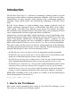
12 Chapter 2. Hardware Installation and Operating System Configuration Table 2-2. Improving Availability and Data Integrity Figure 2-1 illustrates a hardware configuration with improved availability. This configuration uses a fence device (in this case, a network-attached power switch) and the nodes are configured for Red Hat GFS storage attached to a Fibre Channel SAN switch. For more information about configuring and using Red Hat GFS, refer to the Red Hat GFS Administrator’s Guide. Figure 2-1.
Chapter 2.
14 Chapter 2. Hardware Installation and Operating System Configuration switch or network hub, which enables the connection of the nodes to a network. A cluster may also include a console switch, which facilitates the management of multiple nodes and eliminates the need for separate monitors, mouses, and keyboards for each node. One type of console switch is a terminal server, which enables connection to serial consoles and management of many nodes from one remote location.
Chapter 2. Hardware Installation and Operating System Configuration 15 Hardware Quantity Description Cluster nodes 16 (maximum supported) Each node must provide enough PCI slots, Yes network slots, and storage adapters for the cluster hardware configuration. Because attached storage devices must have the same device special file on each node, it is recommended that the nodes have symmetric I/O subsystems.
16 Chapter 2. Hardware Installation and Operating System Configuration tables. Hardware Quantity Description Network interface One for each Each network connection requires a network network interface installed in a node. connection Yes Network switch or hub One Yes Network cable One for each A conventional network cable, such as a Yes network cable with an RJ45 connector, connects interface each network interface to a network switch or a network hub.
Chapter 2. Hardware Installation and Operating System Configuration 17 Hardware Quantity Description External disk storage enclosure At least one Use Fibre Channel or single-initiator Yes parallel SCSI to connect the cluster nodes to a single or dual-controller RAID array. To use single-initiator buses, a RAID controller must have multiple host ports and provide simultaneous access to all the logical units on the host ports.
18 Chapter 2. Hardware Installation and Operating System Configuration Hardware Quantity Description Required Fibre Channel cable As required by hardware configuration A Fibre Channel cable connects a host bus adapter to a storage enclosure port, a Fibre Channel hub, or a Fibre Channel switch. If a hub or switch is used, additional cables are needed to connect the hub or switch to the storage adapter ports. Only for Fibre Channel configurations Table 2-7.
Chapter 2. Hardware Installation and Operating System Configuration 19 connect the nodes to the optional console switch and network switch or hub. Follow these steps: 1. In all nodes, install the required network adapters and host bus adapters. Refer to Section 2.3.1 Installing the Basic Cluster Hardware for more information about performing this task. 2. Set up the optional console switch and connect it to each node. Refer to Section 2.3.
20 Chapter 2. Hardware Installation and Operating System Configuration Cluster Hardware Component Serial Ports Point-to-point Ethernet connection for 2-node clusters (optional) Terminal server connection (optional) Ethernet PCI Ports Slots One for each connection One Table 2-10. Installing the Basic Cluster Hardware Most systems come with at least one serial port. If a system has graphics display capability, it is possible to use the serial console port for a power switch connection.
Chapter 2. Hardware Installation and Operating System Configuration 21 cluster nodes (for example, boot and system partitions, and other file systems that are not associated with any cluster services). An exception to this rule is CLVM, the daemon and library that supports clustering of LVM2.
22 Chapter 2. Hardware Installation and Operating System Configuration 2.3.4. Setting Up a Network Switch or Hub A network switch or hub, although not required for operating a two-node cluster, can be used to facilitate cluster and client system network operations. Clusters of more than two nodes require a switch or hub. Set up a network switch or hub according to the documentation provided by the vendor.
Chapter 2. Hardware Installation and Operating System Configuration 23 3. When using a terminal server, configure Red Hat Enterprise Linux to send console messages to the console port. 4. Edit the /etc/hosts file on each cluster node and include the IP addresses used in the cluster or ensure that the addresses are in DNS. Refer to Section 2.4.1 Editing the /etc/hosts File for more information about performing this task. 5. Decrease the alternate kernel boot timeout limit to reduce boot time for nodes.
24 Chapter 2. Hardware Installation and Operating System Configuration The following is an example of an /etc/hosts file on a node of a cluster that does not use DNS-assigned hostnames: 127.0.0.1 192.168.1.81 193.186.1.82 193.186.1.83 localhost.localdomain node1.example.com node2.example.com node3.example.com localhost node1 node2 node3 The previous example shows the IP addresses and hostnames for three nodes (node1, node2, and node3), Important Do not assign the node hostname to the localhost (127.0.
Chapter 2. Hardware Installation and Operating System Configuration 25 2.4.2. Decreasing the Kernel Boot Timeout Limit It is possible to reduce the boot time for a node by decreasing the kernel boot timeout limit. During the Red Hat Enterprise Linux boot sequence, the boot loader allows for specifying an alternate kernel to boot. The default timeout limit for specifying a kernel is ten seconds.
26 May May May May May May May May May May May May May May Chapter 2.
Chapter 2.
28 Chapter 2. Hardware Installation and Operating System Configuration 2.5. Setting Up and Connecting the Cluster Hardware After installing Red Hat Enterprise Linux, set up the cluster hardware components and verify the installation to ensure that the nodes recognize all the connected devices. Note that the exact steps for setting up the hardware depend on the type of configuration. Refer to Section 2.1 Choosing a Hardware Configuration for more information about cluster configurations.
Chapter 2. Hardware Installation and Operating System Configuration 29 6. Set up the bonded Ethernet channels, if applicable. Refer Section 2.5.1 Configuring Ethernet Channel Bonding for more information. to 7. Run the ping command to verify packet transmission between all cluster nodes. 2.5.1.
30 Chapter 2. Hardware Installation and Operating System Configuration NETMASK=255.255.255.0 GATEWAY=192.168.1.1 IPADDR=192.168.1.10 4. Reboot the system for the changes to take effect. 2.5.2. Configuring a Fence Device Fence devices enable a node to power-cycle another node before restarting its services as part of the failover process. The ability to remotely disable a node ensures data integrity is maintained under any failure condition.
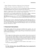
Chapter 2. Hardware Installation and Operating System Configuration 31 2.5.3. Configuring UPS Systems Uninterruptible power supplies (UPS) provide a highly-available source of power. Ideally, a redundant solution should be used that incorporates multiple UPS systems (one per server). For maximal fault-tolerance, it is possible to incorporate two UPS systems per server as well as APC Automatic Transfer Switches to manage the power and shutdown management of the server.
32 Chapter 2. Hardware Installation and Operating System Configuration Figure 2-3. Single UPS System Configuration Many vendor-supplied UPS systems include Red Hat Enterprise Linux applications that monitor the operational status of the UPS system through a serial port connection. If the battery power is low, the monitoring software initiates a clean system shutdown. As this occurs, the cluster software is properly stopped, because it is controlled by a SysV runlevel script (for example, /etc/rc.d/init.
Chapter 2. Hardware Installation and Operating System Configuration 33 beginning of the given range. The following example shows how to create two partitions of 20 MB each on an empty disk. (parted) mkpart primary ext3 0 20 (parted) mkpart primary ext3 20 40 (parted) p Disk geometry for /dev/sda: 0.000-4340.294 megabytes Disk label type: msdos Minor Start End Type Filesystem Flags 1 0.030 21.342 primary 2 21.343 38.
34 Chapter 2. Hardware Installation and Operating System Configuration 6 • 998.872 2001.952 logical A partition may be removed using parted’s rm command. For example: (parted) rm 1 (parted) p Disk geometry for /dev/sda: 0.000-4340.294 megabytes Disk label type: msdos Minor Start End Type Filesystem Flags 2 21.343 38.417 primary 3 38.417 2001.952 extended 5 38.447 998.841 logical 6 998.872 2001.952 logical • After all required partitions have been created, exit parted using the quit command.
Chapter 3. Installing and Configuring Red Hat Cluster Suite Software This chapter describes how to install and configure Red Hat Cluster Suite software and consists of the following sections: • Section 3.1 Software Installation and Configuration Tasks • Section 3.2 Overview of the Cluster Configuration Tool • Section 3.3 Installing the Red Hat Cluster Suite Packages • Section 3.4 Starting the Cluster Configuration Tool • Section 3.5 Naming The Cluster • Section 3.
36 Chapter 3. Installing and Configuring Red Hat Cluster Suite Software 5. Creating cluster members. Refer to Section 3.7 Adding and Deleting Members. 6. Creating failover domains. Refer to Section 3.8 Configuring a Failover Domain. 7. Creating resources. Refer to Section 3.9 Adding Cluster Resources. 8. Creating cluster services. Refer to Section 3.10 Adding a Cluster Service to the Cluster. 9. Propagating the configuration file to the other nodes in the cluster. Refer to Section 3.
Chapter 3. Installing and Configuring Red Hat Cluster Suite Software 37 Figure 3-1. Cluster Configuration Tool The Cluster Configuration Tool uses a hierarchical structure to show relationships among components in the cluster configuration. A triangle icon to the left of a component name indicates that the component has one or more subordinate components assigned to it. To expand or collapse the portion of the tree below a component, click the triangle icon.
38 • Chapter 3. Installing and Configuring Red Hat Cluster Suite Software Managed Resources — Defines failover domains, resources, and services. • • • Failover Domains — Use this section to configure one or more subsets of cluster nodes used to run a service in the event of a node failure. Failover domains are represented as subordinate elements under Failover Domains.
Chapter 3. Installing and Configuring Red Hat Cluster Suite Software 39 Figure 3-2. Cluster Configuration Structure 3.3. Installing the Red Hat Cluster Suite Packages You can install Red Hat Cluster Suite and (optionally install) Red Hat GFS RPMs automatically by running the up2date utility at each node for the Red Hat Cluster Suite and Red Hat GFS products.
40 Chapter 3. Installing and Configuring Red Hat Cluster Suite Software To automatically install RPMs, follow these steps at each node: 1. Log on as the root user. 2. Run up2date --installall --channel Label for Red Hat Cluster Suite. The following example shows running the command for i386 RPMs: # up2date --installall --channel rhel-i386-as-4-cluster 3. (Optional) If you are installing Red Hat GFS, run up2date --installall --channel Label for Red Hat GFS.
Chapter 3. Installing and Configuring Red Hat Cluster Suite Software 41 Figure 3-3. Starting a New Configuration File Note The Cluster Management tab for the Red Hat Cluster Suite management GUI is available after you save the configuration file with the Cluster Configuration Tool, exit, and restart the the Red Hat Cluster Suite management GUI (system-config-cluster).
42 Chapter 3. Installing and Configuring Red Hat Cluster Suite Software 2. Starting the Cluster Configuration Tool displays a graphical representation of the configuration (Figure 3-5) as specified in the cluster configuration file, /etc/cluster/cluster.conf. Figure 3-5. The Cluster Configuration Tool 3.5. Naming The Cluster Naming the cluster consists of specifying a cluster name, a configuration version (optional), and values for Post-Join Delay and Post-Fail Delay. Name the cluster as follows: 1.
Chapter 3. Installing and Configuring Red Hat Cluster Suite Software 43 3. At the Name text box, specify a name for the cluster. The name should be descriptive enough to distinguish it from other clusters and systems on your network (for example, nfs_cluster or httpd_cluster). The cluster name cannot exceed 15 characters. Tip Choose the cluster name carefully. The only way to change the name of a Red Hat cluster is to create a new cluster configuration with the new name. 4.
44 Chapter 3. Installing and Configuring Red Hat Cluster Suite Software To configure fence devices, follow these steps: 1. Click Fence Devices. At the bottom of the right frame (labeled Properties), click the Add a Fence Device button. Clicking Add a Fence Device causes the Fence Device Configuration dialog box to be displayed (refer to Figure 3-6). Figure 3-6. Fence Device Configuration 2.
Chapter 3. Installing and Configuring Red Hat Cluster Suite Software Field Description Name A name for the Brocade device connected to the cluster. IP Address The IP address assigned to the device. Login The login name used to access the device. Password The password used to authenticate the connection to the device. 45 Table 3-2. Configuring a Brocade Fibre Channel Switch Field Description IP Address The IP address assigned to the PAP console.
46 Chapter 3. Installing and Configuring Red Hat Cluster Suite Software Field Description Name A name for the GNBD device used to fence the cluster. Note that the GFS server must be accessed via GNBD for cluster node fencing support. Server The hostname of each GNBD to disable. For multiple hostnames, separate each hostname with a space. Table 3-6. Configuring a Global Network Block Device (GNBD) fencing agent Field Description Name A name for the server with HP iLO support.
Chapter 3. Installing and Configuring Red Hat Cluster Suite Software 47 Field Description IP Address The IP address assigned to the IPMI port. Login The login name of a user capable of issuing power on/off commands to the given IPMI port. Password The password used to authenticate the connection to the IPMI port. Table 3-10. Configuring an Intelligent Platform Management Interface (IPMI) Field Description Name A name to assign the Manual fencing agent.
48 Chapter 3. Installing and Configuring Red Hat Cluster Suite Software Field Description Name A name for the SANBox2 device connected to the cluster. IP Address The IP address assigned to the device. Login The login name used to access the device. Password The password used to authenticate the connection to the device. Table 3-14. Configuring a QLogic SANBox2 Switch Field Description Name A name for the Vixel switch connected to the cluster.
Chapter 3. Installing and Configuring Red Hat Cluster Suite Software 49 3.7.1. Adding a Member to a Cluster To add a member to a new cluster, follow these steps: 1. Click Cluster Node. 2. At the bottom of the right frame (labeled Properties), click the Add a Cluster Node button. Clicking that button causes a Node Properties dialog box to be displayed. For a DLM cluster, the Node Properties dialog box presents text boxes for Cluster Node Name and Quorum Votes (refer to Figure 3-7).
50 Chapter 3. Installing and Configuring Red Hat Cluster Suite Software Note The node on which you are running the Cluster Configuration Tool must be explicitly added as a cluster member; the node is not automatically added to the cluster configuration as a result of running the Cluster Configuration Tool. 4. Optionally, at the Quorum Votes text box, you can specify a value; however in most configurations you can leave it blank.
Chapter 3. Installing and Configuring Red Hat Cluster Suite Software 51 8. Choose File => Save to save the changes to the cluster configuration. 3.7.2. Adding a Member to a Running Cluster The procedure for adding a member to a running cluster depends on whether the cluster contains only two nodes or more than two nodes. To add a member to a running cluster, follow the steps in one of the following sections according to the number of nodes in the cluster: • For clusters with only two nodes — Section 3.
52 Chapter 3. Installing and Configuring Red Hat Cluster Suite Software 6. Start cluster software on all cluster nodes (including the added one) by running the following commands in this order: a. service ccsd start b. service cman start c. service fenced start d. service clvmd start e. service gfs start, if you are using Red Hat GFS f. service rgmanager start 7. Start the Red Hat Cluster Suite management GUI. At the Cluster Configuration Tool tab, verify that the configuration is correct.
Chapter 3. Installing and Configuring Red Hat Cluster Suite Software 53 5. Start the Red Hat Cluster Suite management GUI. At the Cluster Configuration Tool tab, verify that the configuration is correct. At the Cluster Status Tool tab verify that the nodes and services are running as expected. 3.7.3. Deleting a Member from a Cluster To delete a member from an existing cluster that is currently in operation, follow these steps: 1.
54 Chapter 3. Installing and Configuring Red Hat Cluster Suite Software d. At that dialog box, click Yes to confirm deletion. e. Propagate the updated configuration by clicking the Send to Cluster button. (Propagating the updated configuration automatically saves the configuration.) 4. Stop the cluster software on the all remaining running nodes (including GULM lockserver nodes for GULM clusters) by running the following commands at each node in this order: a. service rgmanager stop b.
Chapter 3. Installing and Configuring Red Hat Cluster Suite Software 55 • Unrestricted — Allows you to specify that a subset of members are preferred, but that a cluster service assigned to this domain can run on any available member. • Restricted — Allows you to restrict the members that can run a particular cluster service. If none of the members in a restricted failover domain are available, the cluster service cannot be started (either manually or by the cluster software).
56 Chapter 3. Installing and Configuring Red Hat Cluster Suite Software 2. At the bottom of the right frame (labeled Properties), click the Create a Failover Domain button. Clicking the Create a Failover Domain button causes the Add Failover Domain dialog box to be displayed. 3. At the Add Failover Domain dialog box, specify a failover domain name at the Name for new Failover Domain text box and click OK. Clicking OK causes the Failover Domain Configuration dialog box to be displayed (Figure 3-10).
Chapter 3. Installing and Configuring Red Hat Cluster Suite Software 57 Figure 3-11. Failover Domain Configuration: Adjusting Priority b. For each node that requires a priority adjustment, click the node listed in the Member Node/Priority columns and adjust priority by clicking one of the Adjust Priority arrows. Priority is indicated by the position in the Member Node column and the value in the Priority column.
58 Chapter 3. Installing and Configuring Red Hat Cluster Suite Software 3.8.2. Removing a Failover Domain To remove a failover domain, follow these steps: 1. At the left frame of the the Cluster Configuration Tool, click the failover domain that you want to delete (listed under Failover Domains). 2. At the bottom of the right frame (labeled Properties), click the Delete Failover Domain button.
Chapter 3. Installing and Configuring Red Hat Cluster Suite Software 59 5. At the Cluster Configuration Tool, perform one of the following actions depending on whether the configuration is for a new cluster or for one that is operational and running: • New cluster — If this is a new cluster, choose File => Save to save the changes to the cluster configuration.
60 Chapter 3. Installing and Configuring Red Hat Cluster Suite Software File System Type — Choose the file system for the resource using the dropdown menu. Mount Point — Choose the path to which the file system resource is mounted. Device — Specify the device file associated with the file system resource. Options — Options to pass to the mkfs call for the new file system. File System ID — When creating a new file system resource, you can leave this field blank.
Chapter 3. Installing and Configuring Red Hat Cluster Suite Software 61 NFS Client Name — Enter a name for the NFS client resource. Target — Enter a target for the NFS client resource. Supported targets are hostnames, IP addresses (with wild-card support), and netgroups. Read-Write and Read Only options — Specify the type of access rights for this NFS client resource: • Read-Write — Specifies that the NFS client has read-write access. The default setting is Read-Write.
62 Chapter 3. Installing and Configuring Red Hat Cluster Suite Software 3.10. Adding a Cluster Service to the Cluster To add a cluster service to the cluster, follow these steps: 1. At the left frame, click Services. 2. At the bottom of the right frame (labeled Properties), click the Create a Service button. Clicking Create a Service causes the Add a Service dialog box to be displayed. 3. At the Add a Service dialog box, type the name of the service in the Name text box and click OK.
Chapter 3. Installing and Configuring Red Hat Cluster Suite Software 63 6. Run Exclusive checkbox — This sets a policy wherein the service only runs on nodes that have no other services running on them. For example, for a very busy web server that is clustered for high availability, it would would be advisable to keep that service on a node alone with no other services competing for his resources — that is, Run Exclusive checked.
64 Chapter 3. Installing and Configuring Red Hat Cluster Suite Software Note To verify the existence of the IP service resource used in a cluster service, you must use the /sbin/ip addr list command on a cluster node. The following output shows the /sbin/ip addr list command executed on a node running a cluster service: 1: lo: mtu 16436 qdisc noqueue link/loopback 00:00:00:00:00:00 brd 00:00:00:00:00:00 inet 127.0.0.
Chapter 3. Installing and Configuring Red Hat Cluster Suite Software 65 1. service ccsd start 2. service lock_gulmd start or service cman start according to the type of lock manager used 3. service fenced start (DLM clusters only) 4. service clvmd start 5. service gfs start, if you are using Red Hat GFS 6. service rgmanager start 7. Start the Red Hat Cluster Suite management GUI. At the Cluster Configuration Tool tab, verify that the configuration is correct.
66 Chapter 3.
Chapter 4. Cluster Administration This chapter describes the various administrative tasks for maintaining a cluster after it has been installed and configured. 4.1. Overview of the Cluster Status Tool The Cluster Status Tool is part of the Red Hat Cluster Suite management GUI, (the system-config-cluster package) and is accessed by a tab in the Red Hat Cluster Suite management GUI. The Cluster Status Tool displays the status of cluster members and services and provides control of cluster services.
68 Chapter 4. Cluster Administration Figure 4-1. Cluster Status Tool 4.2. Displaying Cluster and Service Status Monitoring cluster and application service status can help identify and resolve problems in the cluster environment. The following tools assist in displaying cluster status information: • The Cluster Status Tool • The clustat utility Important Members that are not running the cluster software cannot determine or report the status of other members of the cluster.
Chapter 4. Cluster Administration 69 Cluster and service status includes the following information: • Cluster member system status • Service status and which cluster system is running the service or owns the service The following tables describe how to analyze the status information shown by the Cluster Status Tool and the clustat utility. Member Status Description Member The node is part of the cluster.
70 Chapter 4. Cluster Administration Service Status Description Started The service resources are configured and available on the cluster system that owns the service. Pending The service has failed on a member and is pending start on another member. Disabled The service has been disabled, and does not have an assigned owner. A disabled service is never restarted automatically by the cluster. Stopped The service is not running; it is waiting for a member capable of starting the service.
Chapter 4. Cluster Administration 71 To monitor the cluster and display status at specific time intervals from a shell prompt, invoke clustat with the -i time option, where time specifies the number of seconds between status snapshots. The following example causes the clustat utility to display cluster status every 10 seconds: #clustat -i 10 4.3. Starting and Stopping the Cluster Software To start the cluster software on a member, type the following commands in this order: 1. service ccsd start 2.
72 Chapter 4. Cluster Administration Warning Do not manually edit the contents of the /etc/cluster/cluster.conf file without guidance from an authorized Red Hat representative or unless you fully understand the consequences of editing the /etc/cluster/cluster.conf file manually. Important Although the Cluster Configuration Tool provides a Quorum Votes parameter in the Properties dialog box of each cluster member, that parameter is intended only for use during initial cluster configuration.
Chapter 4. Cluster Administration 73 4.5. Backing Up and Restoring the Cluster Database The Cluster Configuration Tool automatically retains backup copies of the three most recently used configuration files (besides the currently used configuration file). Retaining the backup copies is useful if the cluster does not function correctly because of misconfiguration and you need to return to a previous working configuration.
74 Chapter 4. Cluster Administration Note The Cluster Configuration Tool does not display the Send to Cluster button if the cluster is new and has not been started yet, or if the node from which you are running the Cluster Configuration Tool is not a member of the cluster. If the Send to Cluster button is not displayed, you can still use the Cluster Configuration Tool; however, you cannot propagate the configuration. You can still save the configuration file.
Chapter 4.
76 Chapter 4.
Chapter 5. Setting Up Apache HTTP Server This chapter contains instructions for configuring Red Hat Enterprise Linux to make the Apache HTTP Server highly available. The following is an example of setting up a cluster service that fails over an Apache HTTP Server. Although the actual variables used in the service depend on the specific configuration, the example may assist in setting up a service for a particular environment. 5.1.
78 Chapter 5. Setting Up Apache HTTP Server 5.2. Configuring Shared Storage To set up the shared file system resource, perform the following tasks as root on one cluster system: 1. On one cluster node, use the interactive parted utility to create a partition to use for the document root directory. Note that it is possible to create multiple document root directories on different disk partitions. Refer to Section 2.5.3.1 Partitioning Disks for more information. 2.
Chapter 5. Setting Up Apache HTTP Server • 79 Specify a unique IP address to which the service will listen for requests. For example: Listen 192.168.1.100:80 This IP address then must be configured as a cluster resource for the service using the Cluster Configuration Tool. • If the script directory resides in a non-standard location, specify the directory that contains the CGI programs.
80 Chapter 5. Setting Up Apache HTTP Server 2. Add a device for the Apache HTTP Server content files and/or custom scripts. • Click Create a Resource. • In the Resource Configuration dialog, select File System from the drop-down menu. • Enter the Name for the resource (for example, httpd-content. • Choose ext3 from the File System Type drop-down menu. • Enter the mount point /var/www/html/). • Enter the device special file name in the Device field (for example, /dev/sda3).
II. Configuring a Linux Virtual Server Cluster Building a Linux Virtual Server (LVS) system offers highly-available and scalable solution for production services using specialized routing and load-balancing techniques configured through the Piranha Configuration Tool. This part discusses the configuration of highperformance systems and services with Red Hat Enterprise Linux and LVS. This section is licensed under the Open Publication License, V1.0 or later. For details refer to the Copyright page.
Chapter 6. Introduction to Linux Virtual Server Using Red Hat Enterprise Linux, it is possible to create highly available server clustering solutions able to withstand many common hardware and software failures with little or no interruption of critical services. By allowing multiple computers to work together in offering these critical services, system administrators can plan and execute system maintenance and upgrades without service interruption.
84 Chapter 6. Introduction to Linux Virtual Server hardware to implement a fully redundant environment in which services can run uninterrupted by hardware failures. However, fault tolerant systems do not account for operator and software errors which Red Hat Enterprise Linux can address through service redundancy.
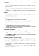
Chapter 7. Linux Virtual Server Overview Red Hat Enterprise Linux LVS clustering uses a Linux machine called the active router to send requests from the Internet to a pool of servers. To accomplish this, LVS clusters consist of two basic machine classifications — the LVS routers (one active and one backup) and a pool of real servers which provide the critical services. The active router serves two roles in the cluster: • To balance the load on the real servers.
86 Chapter 7. Linux Virtual Server Overview Figure 7-1. A Basic LVS Configuration Service requests arriving at the LVS cluster are addressed to a virtual IP address or VIP. This is a publicly-routable address the administrator of the site associates with a fullyqualified domain name, such as www.example.com, and which is assigned to one or more virtual server 1.
Chapter 7. Linux Virtual Server Overview 87 The active router also dynamically monitors the overall health of the specific services on the real servers through simple send/expect scripts. To aid in detecting the health of services that require dynamic data, such as HTTPS or SSL, the administrator can also call external executables. If a service on a real server malfunctions, the active router stops sending jobs to that server until it returns to normal operation.
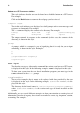
88 Chapter 7. Linux Virtual Server Overview 7.2. A Three Tiered LVS Configuration Figure 7-2 shows a typical three tiered LVS cluster topology. In this example, the active LVS router routes the requests from the Internet to the pool of real servers. Each of the real servers then accesses a shared data source over the network. Figure 7-2.
Chapter 7. Linux Virtual Server Overview 89 cluster to serve both of these roles simultaneously. The third tier in the above example does not have to use Red Hat Cluster Manager, but failing to use a highly available solution would introduce a critical single point of failure. 7.3. LVS Scheduling Overview One of the advantages of using an LVS cluster is its ability to perform flexible, IP-level load balancing on the real server pool.
90 Chapter 7. Linux Virtual Server Overview that it is network-connection based and not host-based. LVS round-robin scheduling also does not suffer the imbalances caused by cached DNS queries. Weighted Round-Robin Scheduling Distributes each request sequentially around the pool of real servers but gives more jobs to servers with greater capacity. Capacity is indicated by a user-assigned weight factor, which is then adjusted upward or downward by dynamic load information. Refer to Section 7.3.
Chapter 7. Linux Virtual Server Overview 91 the real server with the least connections from the overall pool of real servers to the subset of real servers for that destination IP. The most loaded node is then dropped from the real server subset to prevent over-replication. Destination Hash Scheduling Distributes requests to the pool of real servers by looking up the destination IP in a static hash table. This algorithm is designed for use in a proxy-cache server cluster.
92 Chapter 7. Linux Virtual Server Overview 7.4.1. NAT Routing Figure 7-3, illustrates an LVS cluster utilizing NAT routing to move requests between the Internet and a private network. Figure 7-3. An LVS Cluster Implemented with NAT Routing In the example, there are two NICs in the active LVS router. The NIC for the Internet has a real IP address on eth0 and has a floating IP address aliased to eth0:1.
Chapter 7. Linux Virtual Server Overview 93 In this example, the LVS router’s public LVS floating IP address and private NAT floating IP address are aliased to two physical NICs. While it is possible to associate each floating IP address to its own physical device on the LVS router nodes, having more than two NICs is not a requirement. Using this topography, the active LVS router receives the request and routes it to the appropriate server.
94 Chapter 7. Linux Virtual Server Overview 7.5.2. Firewall Marks Firewall marks are an easy and efficient way to a group ports used for a protocol or group of related protocols. For instance, if an LVS cluster is deployed to run an e-commerce site, firewall marks can be used to bundle HTTP connections on port 80 and secure, HTTPS connections on port 443.
Chapter 7. Linux Virtual Server Overview 95 The pulse daemon runs on both the active and passive LVS routers. On the backup router, pulse sends a heartbeat to the public interface of the active router to make sure the active router is still properly functioning. On the active router, pulse starts the lvs daemon and responds to heartbeat queries from the backup LVS router.
96 Chapter 7. Linux Virtual Server Overview 7.6.1.3. ipvsadm This service updates the IPVS routing table in the kernel. The lvs daemon sets up and administers an LVS cluster by calling ipvsadm to add, change, or delete entries in the IPVS routing table. 7.6.1.4. nanny The nanny monitoring daemon runs on the active LVS router. Through this daemon, the active router determines the health of each real server and, optionally, monitors its workload.
Chapter 8. Initial LVS Configuration After installing Red Hat Enterprise Linux, you must take some basic steps to set up both the LVS routers and the real servers in the LVS cluster. This chapter covers these initial steps in detail. Note The LVS router node that becomes the active node once the cluster is started is also referred to as the primary node. When configuring an LVS cluster, use the Piranha Configuration Tool on the primary node. 8.1.
98 Chapter 8. Initial LVS Configuration If you are clustering multi-port services or using firewall marks, you must also enable the iptables service. It is best to set these services to activate in both runlevel 3 and runlevel 5. To accomplish this using chkconfig, type the following command for each service: /sbin/chkconfig --level 35 daemon on In the above command, replace daemon with the name of the service you are activating.
Chapter 8. Initial LVS Configuration 99 If the password is changed during an active Piranha Configuration Tool session, the administrator is prompted to provide the new password. 8.3. Starting the Piranha Configuration Tool Service After you have set the password for the Piranha Configuration Tool, start or restart the piranha-gui service located in /etc/rc.d/init.d/piranha-gui.
100 Chapter 8. Initial LVS Configuration 8.3.1. Configuring the Piranha Configuration Tool Web Server Port The Piranha Configuration Tool runs on port 3636 by default. To change this port number, change the line Listen 3636 in Section 2 of the piranha-gui Web server configuration file /etc/sysconfig/ha/conf/httpd.conf. To use the Piranha Configuration Tool you need at minimum a text-only Web browser. If you start a Web browser on the primary LVS router, open the location http://localhost:3636.
Chapter 8. Initial LVS Configuration 101 You can also allow specific hosts or subnets as seen in this example: Order deny,allow Deny from all Allow from 192.168.1.100 Allow from 172.16.57 In this example, only Web browsers from the machine with the IP address of 192.168.1.100 and machines on the 172.16.57/24 network can access the Piranha Configuration Tool. Caution Editing the Piranha Configuration Tool .
102 Chapter 8. Initial LVS Configuration 8.6. Configuring Services on the Real Servers If the real servers in the cluster are Red Hat Enterprise Linux systems, set the appropriate server daemons to activate at boot time. These daemons can include httpd for Web services or xinetd for FTP or Telnet services. It may also be useful to access the real servers remotely, so the sshd daemon should also be installed and running.
Chapter 9. Setting Up a Red Hat Enterprise Linux LVS Cluster A Red Hat Enterprise Linux LVS cluster consists of two basic groups: the LVS routers and the real servers. To prevent a single point of failure, each groups should contain at least two member systems. The LVS router group should consist of two identical or very similar systems running Red Hat Enterprise Linux.
104 Chapter 9. Setting Up a Red Hat Enterprise Linux LVS Cluster ration Tool. In particular, FTP services and the use of firewall marks requires extra manual configuration of the LVS routers to route requests properly. 9.1.1. Configuring Network Interfaces for a NAT LVS Cluster To set up a NAT LVS cluster, the administrator must first configure the network interfaces for the public network and the private network on the LVS routers.
Chapter 9. Setting Up a Red Hat Enterprise Linux LVS Cluster 105 After configuring the primary LVS router node’s network interfaces, configure the backup LVS router’s real network interfaces — taking care that none of the IP address conflict with any other IP addresses on the network. Important Be sure each interface on the backup node services the same network as the interface on primary node.
106 Chapter 9. Setting Up a Red Hat Enterprise Linux LVS Cluster It is best to turn off extraneous network interfaces by setting ONBOOT=no in their network scripts within the /etc/sysconfig/network-scripts/ directory or by making sure the gateway is correctly set in the interface which comes up first. 9.1.3.
Chapter 9. Setting Up a Red Hat Enterprise Linux LVS Cluster 107 Important The adapter devices on the LVS routers must be configured to access the same networks. For instance if eth0 connects to public network and eth1 connects to the private network, then these same devices on the backup LVS router must connect to the same networks. Also the gateway listed in the first interface to come up at boot time is added to the routing table and subsequent gateways listed in other interfaces are ignored.
108 Chapter 9. Setting Up a Red Hat Enterprise Linux LVS Cluster Checking the Status of Network Interfaces If you need to check which network interfaces are up at any given time, type the following: /sbin/ifconfig To view the routing table for a machine, issue the following command: /sbin/route 9.3. Multi-port Services and LVS Clustering LVS routers under any topology require extra configuration when creating multi-port LVS services.
Chapter 9. Setting Up a Red Hat Enterprise Linux LVS Cluster 109 If iptables is active, it displays a set of rules. If rules are present, type the following command: /sbin/service iptables stop If the rules already in place are important, check the contents of /etc/sysconfig/iptables and copy any rules worth keeping to a safe place before proceeding. Below are rules which assign the same firewall mark, 80, to incoming traffic destined for the floating IP address, n.n.n.
110 Chapter 9. Setting Up a Red Hat Enterprise Linux LVS Cluster an FTP client connects to an FTP server it opens a connection to the FTP control port 21. Then the client tells the FTP server whether to establish an active or passive connection. The type of connection chosen by the client determines how the server responds and on what ports transactions will occur.
Chapter 9. Setting Up a Red Hat Enterprise Linux LVS Cluster 111 9.4.3. Creating Network Packet Filter Rules Before assigning any iptables rules for FTP service, review the information in Section 9.3.1 Assigning Firewall Marks concerning multi-port services and techniques for checking the existing network packet filtering rules. Below are rules which assign the same firewall mark, 21, to FTP traffic.
112 Chapter 9. Setting Up a Red Hat Enterprise Linux LVS Cluster pasv_address=X.X.X.X Replace X.X.X.X with the VIP address of the LVS system. For configuration of other FTP servers, consult the respective documentation. This range should be a wide enough for most situations; however, you can increase this number to include all available non-secured ports by changing 10000:20000 in the commands below to 1024:65535. iptables /sbin/iptables -t mangle -A PREROUTING -p tcp \ -d n.n.n.
Chapter 9. Setting Up a Red Hat Enterprise Linux LVS Cluster 113 This saves the settings in /etc/sysconfig/iptables so they can be recalled at boot time. Once this file is written, you are able to use the /sbin/service command to start, stop, and check the status (using the status switch) of iptables. The /sbin/service will automatically load the appropriate module for you. For an example of how to use the /sbin/service command, see Section 8.3 Starting the Piranha Configuration Tool Service.
114 Chapter 9.
Chapter 10. Configuring the LVS Routers with Piranha Configuration Tool The Piranha Configuration Tool provides a structured approach to creating the necessary configuration file for a Piranha cluster — /etc/sysconfig/ha/lvs.cf. This chapter describes the basic operation of the Piranha Configuration Tool and how to activate the cluster once configuration is complete. Important The configuration file for the LVS cluster follows strict formatting rules.
116 Chapter 10. Configuring the LVS Routers with Piranha Configuration Tool or real IP address for the server followed by :3636. Once the browser connects, you will see the screen shown in Figure 10-1. Figure 10-1. The Welcome Panel Click on the Login button and enter piranha for the Username and the administrative password you created in the Password field. The Piranha Configuration Tool is made of four main screens or panels. In addition, the Virtual Servers panel contains four subsections.
Chapter 10. Configuring the LVS Routers with Piranha Configuration Tool 117 Figure 10-2. The CONTROL/MONITORING Panel Auto update The status display on this page can be updated automatically at a user configurable interval. To enable this feature, click on the Auto update checkbox and set the desired update frequency in the Update frequency in seconds text box (the default value is 10 seconds). It is not recommended that you set the automatic update to an interval less than 10 seconds.
118 Chapter 10. Configuring the LVS Routers with Piranha Configuration Tool The Auto update feature does not work with all browsers, such as Mozilla. Update information now You can manually update the status information manually by clicking this button. CHANGE PASSWORD Clicking this button takes you to a help screen with information on how to change the administrative password for the Piranha Configuration Tool. 10.4.
Chapter 10. Configuring the LVS Routers with Piranha Configuration Tool 119 Figure 10-3. The GLOBAL SETTINGS Panel The top half of this panel sets up the primary LVS router’s public and private network interfaces. These are the interfaces already configured in Section 9.1.1 Configuring Network Interfaces for a NAT LVS Cluster. Primary server public IP In this field, enter the publicly routable real IP address for the primary LVS node.
120 Chapter 10. Configuring the LVS Routers with Piranha Configuration Tool Tip The primary LVS router’s private IP can be configured on any interface that accepts TCP/IP, whether it be an Ethernet adapter or a serial port. Use network type Click the NAT button to select NAT routing. The next three fields deal specifically with the NAT router’s virtual network interface connected the private network with the real servers. NAT Router IP Enter the private floating IP in this text field.
Chapter 10. Configuring the LVS Routers with Piranha Configuration Tool 121 Tip The first time you visit this screen, it displays an "inactive" Backup status and an ENABLE button. To configure the backup LVS router, click on the ENABLE button so that the screen matches Figure 10-4. Figure 10-4. The REDUNDANCY Panel Redundant server public IP Enter the public real IP address for the backup LVS router node.
122 Chapter 10. Configuring the LVS Routers with Piranha Configuration Tool Redundant server private IP Enter the backup node’s private real IP address in this text field. If you do not see the field called Redundant server private IP, go back to the GLOBAL SETTINGS panel and enter a Primary server private IP address and click ACCEPT. The rest of the panel is devoted to configuring the heartbeat channel, which is used by the backup node to monitor the primary node for failure.
Chapter 10. Configuring the LVS Routers with Piranha Configuration Tool 123 Figure 10-5. The VIRTUAL SERVERS Panel Each server displayed in the VIRTUAL SERVERS panel can be configured on subsequent screens or subsections. To add a service, click the ADD button. To remove a service, select it by clicking the radio button next to the virtual server and click the DELETE button. To enable or disable a virtual server in the table click its radio button and click the (DE)ACTIVATE button.
124 Chapter 10. Configuring the LVS Routers with Piranha Configuration Tool are located along the top of the page. But before configuring any of the subsections related to this virtual server, complete this page and click on the ACCEPT button. Figure 10-6. The VIRTUAL SERVERS Subsection Name Enter a descriptive name to identify the virtual server. This name is not the hostname for the machine, so make it descriptive and easily identifiable.
Chapter 10. Configuring the LVS Routers with Piranha Configuration Tool 125 Protocol Choose between UDP and TCP in the drop-down menu. Web servers typically communicate via the TCP protocol, so this is selected in the example above. Virtual IP Address Enter the virtual server’s floating IP address in this text field. Virtual IP Network Mask Set the netmask for this virtual server with the drop-down menu.
126 Chapter 10. Configuring the LVS Routers with Piranha Configuration Tool Quiesce server When the Quiesce server radio button is selected, anytime a new real server node comes online, the least-connections table is reset to zero so the active LVS router routes requests as if all the real servers were freshly added to the cluster. This option prevents the a new server from becoming bogged down with a high number of connections upon entering the cluster.
Chapter 10. Configuring the LVS Routers with Piranha Configuration Tool 127 Note Before the advent of firewall marks, persistence limited by subnet was a crude way of bundling connections. Now, it is best to use persistence in relation to firewall marks to achieve the same result. Warning Remember to click the ACCEPT button after making any changes in this panel. To make sure you do not lose changes when selecting a new panel. 10.6.2.
128 Chapter 10. Configuring the LVS Routers with Piranha Configuration Tool Figure 10-7. The REAL SERVER Subsection Click the ADD button to add a new server. To delete an existing server, select the radio button beside it and click the DELETE button. Click the EDIT button to load the EDIT REAL SERVER panel, as seen in Figure 10-8.
Chapter 10. Configuring the LVS Routers with Piranha Configuration Tool 129 Figure 10-8. The REAL SERVER Configuration Panel This panel consists of three entry fields: Name A descriptive name for the real server. Tip This name is not the hostname for the machine, so make it descriptive and easily identifiable. Address The real server’s IP address. Since the listening port is already specified for the associated virtual server, do not add a port number.
130 Chapter 10. Configuring the LVS Routers with Piranha Configuration Tool Weight An integer value indicating this host’s capacity relative to that of other hosts in the pool. The value can be arbitrary, but treat it as a ratio in relation to other real servers in the cluster. For more on server weight, see Section 7.3.2 Server Weight and Scheduling. Warning Remember to click the ACCEPT button after making any changes in this panel. To make sure you do not lose any changes when selecting a new panel.
Chapter 10. Configuring the LVS Routers with Piranha Configuration Tool 131 Figure 10-9. The EDIT MONITORING SCRIPTS Subsection Sending Program For more advanced service verification, you can use this field to specify the path to a service-checking script. This functionality is especially helpful for services that require dynamically changing data, such as HTTPS or SSL.
132 Chapter 10. Configuring the LVS Routers with Piranha Configuration Tool The following is a sample script to use as a guide when composing an external servicechecking script: #!/bin/sh TEST=‘dig -t soa example.com @$1 | grep -c dns.example.com if [ $TEST != "1" ]; then echo "OK else echo "FAIL" fi Note If an external program is entered in the Sending Program field, then the Send field is ignored. Send Enter a string for the nanny daemon to send to each real server in this field.
Chapter 10. Configuring the LVS Routers with Piranha Configuration Tool 133 Warning Remember to click the ACCEPT button after making any changes in this panel. To make sure you do not lose any changes when selecting a new panel. Once you have configured virtual servers using the Piranha Configuration Tool, you must copy specific configuration files to the backup LVS router. See Section 10.7 Synchronizing Configuration Files for details. 10.7.
134 Chapter 10. Configuring the LVS Routers with Piranha Configuration Tool The best way to do this is to use the scp command. Important To use scp the sshd must be running on the backup router, see Section 8.1 Configuring Services on the LVS Routers for details on how to properly configure the necessary services on the LVS routers. Issue the following command as the root user from the primary LVS router to sync the lvs.cf files between the router nodes: scp /etc/sysconfig/ha/lvs.cf n.n.n.
Chapter 10. Configuring the LVS Routers with Piranha Configuration Tool 135 Next either open an ssh session to the backup router or log into the machine as root and type the following command: /sbin/service iptables restart Once you have copied these files over to the backup router and started the appropriate services (see Section 8.1 Configuring Services on the LVS Routers for more on this topic) you are ready to start the cluster. 10.8.
136 Chapter 10.
III. Appendixes This section is licensed under the GNU Free Documentation License. For details refer to the Copyright page. Table of Contents A. Supplementary Hardware Information ..................................................................139 B. Selectively Installing Red Hat Cluster Suite Packages ..........................................147 C. Multipath-usage.txt File for Red Hat Enterprise Linux 4 Update 3 .............
Appendix A. Supplementary Hardware Information The following sections provide additional information about configuring the hardware used in a cluster system. A.1. Attached Storage Requirements The following sections detail the steps to consider when directly connecting storage devices to cluster nodes, whether using SCSI host-bus adapters or Fibre Channel connections. A.2. Setting Up a Fibre Channel Interconnect Fibre Channel can be used in either single-initiator or multi-initiator configurations.
140 Appendix A. Supplementary Hardware Information Figure A-1. Single-controller RAID Array Connected to Single-initiator Fibre Channel Interconnects The external RAID array must have a separate SCSI channel for each cluster node. In clusters with more than two nodes, connect each node to the SCSI channel on the RAID array, using a single-initiator SCSI bus as shown in Figure A-1. To connect multiple cluster nodes to the same host port on the RAID array, use a Fibre Channel hub or switch.
Appendix A. Supplementary Hardware Information 141 Figure A-2. Dual-controller RAID Array Connected to Single-initiator Fibre Channel Interconnects A.3. SCSI Storage Requirements A single-initiator SCSI bus has only one node connected to it, and provides host isolation and better performance than a multi-initiator bus. Single-initiator buses ensure that each node is protected from disruptions due to the workload, initialization, or repair of the other nodes.
142 • Appendix A. Supplementary Hardware Information Use the appropriate SCSI cable to connect each host bus adapter to the storage enclosure. Setting host bus adapter termination is done in the adapter BIOS utility during system boot. To set RAID controller termination, refer to the vendor documentation. Figure A-3 shows a configuration that uses two single-initiator SCSI buses. Figure A-3.
Appendix A. Supplementary Hardware Information 143 Figure A-5. Dual-controller RAID Array Connected to Single-initiator SCSI Buses A.3.1. SCSI Configuration Requirements SCSI devices must adhere to a number of configuration requirements to operate correctly. Failure to adhere to these requirements adversely affects cluster operation and resource availability. The following is an overview of SCSI configuration requirements: • Buses must be terminated at each end. Refer to Section A.3.
144 Appendix A. Supplementary Hardware Information A.3.2. SCSI Bus Termination A SCSI bus is an electrical path between two terminators. A device (host bus adapter, RAID controller, or disk) attaches to a SCSI bus by a short stub, which is an unterminated bus segment that usually must be less than 0.1 meter in length. Buses must have only two terminators located at opposing ends of the bus.
Appendix A. Supplementary Hardware Information 145 A cluster supports LVD (low voltage differential) buses. The maximum length of a singleinitiator LVD bus is 25 meters. The maximum length of a multi-initiator LVD bus is 12 meters. According to the SCSI standard, a single-initiator LVD bus is a bus that is connected to only two devices, each within 0.1 meter from a terminator. All other buses are defined as multi-initiator buses.
146 Appendix A.
Appendix B. Selectively Installing Red Hat Cluster Suite Packages B.1.
148 Appendix B. Selectively Installing Red Hat Cluster Suite Packages • gnbd-kernel — Kernel module for the GFS Network Block Device • lvm2-cluster — Cluster extensions for the logical volume manager • GFS-kernheaders — GFS kernel header files • gnbd-kernheaders — gnbd kernel header files Tip You can access the Red Hat Cluster Suite and Red Hat GFS products by using Red Hat Network to subscribe to and access the channels containing the Red Hat Cluster Suite and Red Hat GFS packages.
Appendix B. Selectively Installing Red Hat Cluster Suite Packages 149 2. Run up2date --installall --channel Label for Red Hat Cluster Suite. The following example shows running the command for i386 RPMs: # up2date --installall --channel rhel-i386-as-4-cluster 3. (Optional) If you are installing Red Hat GFS, run up2date --installall --channel Label for Red Hat GFS. The following example shows running the command for i386 RPMs: # up2date --installall --channel rhel-i386-as-4-gfs-6.1 B.1.2.
150 • Appendix B. Selectively Installing Red Hat Cluster Suite Packages Table B-3 — For Red Hat GFS The tables contain the following information to assist you in determining which packages to install: • RPMs — The names of the RPMs (excluding revision numbers) • Inclusion — The tables provide the following information about whether an RPM should be included in the installation: • • Req: Required RPM — You must install the RPM.
Appendix B. Selectively Installing Red Hat Cluster Suite Packages 151 RPMs Inclusion Depends Purpose on Kernel Type? ccs-ver-rel.arch Req No The Cluster Configuration System cman-ver-rel.arch Req No The Cluster Manager cman-kernel-ver-rel.arch Req cman-kernel-hugemem-ver-rel.arch cman-kernel-smp-ver-rel.arch Yes The Cluster Manager kernel modules Req No The Distributed Lock Manager dlm-kernel-ver-rel.arch Req dlm-kernel-hugemem-ver-rel.arch dlm-kernel-smp-ver-rel.
152 Appendix B. Selectively Installing Red Hat Cluster Suite Packages RPMs Inclusion Depends Purpose on Kernel Type? rgmanager-ver-rel.arch Opt No Open source HA resource group failover system-config-cluster-ver-rel.arch Req No GUI to manage cluster configuration ipvsadm-ver-rel.arch Opt No Utility to administer the Linux Virtual Server piranha-ver-rel.arch Opt No Cluster administration tools ccs-devel-ver-rel.arch Dev No CCS static library cman-kernheaders-ver-rel.
Appendix B. Selectively Installing Red Hat Cluster Suite Packages 153 RPMs Inclusion Depends Purpose on Kernel Type? ccs-ver-rel.arch Req No The Cluster Configuration System fence-ver-rel.arch Req No The cluster I/O fencing system gulm-ver-rel.arch Req No The Grand Unified Lock Manager (GULM, available for this release and earlier versions of Red Hat GFS) iddev-ver-rel.arch Req No A library that identifies device contents magma-ver-rel.
154 Appendix B. Selectively Installing Red Hat Cluster Suite Packages RPMs Inclusion Depends Purpose on Kernel Type? magma-devel-ver-rel.arch Dev No A cluster/lock manager API abstraction library Table B-2. RPM Selection Criteria: Red Hat Cluster Suite with GULM RPMs Inclusion Depends Purpose on Kernel Type? GFS-ver-rel.arch Req No The Red Hat GFS module GFS-kernel-ver-rel.arch Req GFS-kernel-hugemem-ver-rel.arch GFS-kernel-smp-ver-rel.
Appendix B. Selectively Installing Red Hat Cluster Suite Packages 155 B.1.2.2. Installing Packages with the rpm Utility You can use the rpm utility to install RPMs from CDs created with RHN ISOs. The procedure consists of copying RPMs to a local computer, removing the RPMs that are not needed for the installation, copying the RPMs to the cluster nodes, and installing them. To install the RPMs, follow these instructions: 1.
156 Appendix B. Selectively Installing Red Hat Cluster Suite Packages Note If your local computer is running a version of Red Hat Enterprise Linux that is earlier than Red Hat Enterprise Linux 4, the path to the RPMs on the CD may be different. For example, on Red Hat Enterprise Linux 3, the path is /mnt/cdrom/RedHat/RPMS/. 7. Eject the CD from the CD-ROM drive. 8. Change to the temporary directory containing the copied RPM files. For example: $ cd /tmp/RPMS/ 9.
Appendix C. Multipath-usage.txt File for Red Hat Enterprise Linux 4 Update 3 This appendix contains the Multipath-usage.txt file. The file is included with the dm-multipath RPM and provides guidelines for using dm-multipath with Red Hat Cluster Suite for Red Hat Enterprise Linux 4 Update 3: RHEL4 U3 Device Mapper Multipath Usage Overview -----------Device Mapper Multipath (DM-MP) allows nodes to route I/O over multiple paths to a storage controller.
Appendix C. Multipath-usage.txt File for Red Hat Enterprise Linux 4 158 Update 3 DM-MP works with a variety of storage arrays.
Appendix C. Multipath-usage.txt File for Red Hat Enterprise Linux 4 Update 3 159 Path States: ready - Path is able to handle I/O requests. shaky - Path is up, but temporarily not available for normal operations. faulty - Path is unable to handle I/O requests. ghost - Path is a passive path, on an active/passive controller. NOTE: The shaky and ghost states only exist for certain storage arrays. Path Group: A grouping of paths.
Appendix C. Multipath-usage.txt File for Red Hat Enterprise Linux 4 160 Update 3 priority path group. Other options for multipathd are to (a) wait for a user-defined length of time (for the path groups to stabilize) and then switch or (b) for multipathd to do nothing and wait for manual intervention. Failback can be forced at any time by running the multipath command. Multipath device: The multipath device is the device mapper device created by dm-multipath.
Appendix C. Multipath-usage.txt File for Red Hat Enterprise Linux 4 Update 3 161 For some conditions, that may not be sufficient. If DM-MP is multipathing devices that you do not want it to work on, you can blacklist the devices by either device name or WWID. NOTE: It is safest to blacklist individual devices by WWID, because their device names may change. Several other configuration options are detailed later in this document.
Appendix C. Multipath-usage.txt File for Red Hat Enterprise Linux 4 162 Update 3 "devnode_blacklist", and "devices" sections of the configuration file. To see what these are, refer to the following file: /usr/share/doc/device-mapper-multipathd-0.4.5/multipath.conf.synthetic If you are using one of the storage arrays listed in the preceding text (in "Overview"), you probably do not need to modify the "devices" subsection. If you are using a simple disk enclosure, the defaults should work.
Appendix C. Multipath-usage.txt File for Red Hat Enterprise Linux 4 Update 3 163 DM-MP cannot be run on either the root or boot device. Other Sources of information ---------------------------Configuration file explanation: /usr/share/doc/device-mapper-multipathd-0.4.5/multipath.conf.annotated Upstream documentation: http://christophe.varoqui.free.fr/wiki/wakka.php?wiki=Home mailing list: dm-devel@redhat.com Subscribe to this from https://www.redhat.com/mailman/listinfo/dm-devel.
Appendix C. Multipath-usage.
Index Symbols /etc/hosts editing, 23 /etc/sysconfig/ha/lvs.cf file, 96 A activating your subscription, vi active router (see LVS clustering) Apache HTTP Server httpd.
166 Beowulf, 83 definition of, 83 high-availability clustering, 83 (see also Red Hat Cluster Manager) definition of, 83 load-balance clustering, 83 (see also LVS clustering) definition of, 83 overview of, 83 components of LVS cluster, 95 compute-clustering (see cluster types) configuration Red Hat Enterprise Linux, 22 configuration file propagation of, 64 console startup messages displaying, 25 console switch, 13 setting up, 21 console switch hardware table, 18 conventions document, ii D displaying console
167 I installation Red Hat Enterprise Linux, 22 installing basic cluster hardware, 19 installing the basic cluster hardware, 19 introduction, i how to use this manual, i other Red Hat Enterprise Linux manuals, i iptables, 97 ipvsadm program, 96 J job scheduling, LVS, 89 K kernel decreasing kernel boot timeout limit, 25 displaying configured devices, 26 Kernel Boot Timeout Limit decreasing, 25 KVM (keyboard, video, mouse) switch, 14 L least connections (see job scheduling, LVS) Linux Virtual Server (see
168 N nanny daemon, 96 NAT enabling, 106 routing methods, LVS, 91 network address translation (see NAT) network hardware table, 16 network hub, 13 network switch, 13 no single point of failure configuration, 13 nodes setting up, 18 O operating system configuration hardware installation, 9 P packet forwarding, 101 (see also LVS clustering) parted creating disk partitions, 32 partitioning disks, 32 Piranha Configuration Tool, 96 CONTROL/MONITORING, 116 EDIT MONITORING SCRIPTS Subsection, 130 GLOBAL SETTING
169 S scheduling, job (LVS), 89 SCSI bus length, 144 SCSI bus termination, 144 SCSI configuration requirements, 143 SCSI identification numbers, 145 SCSI storage requirements, 141 security Piranha Configuration Tool, 100 send_arp program, 96 service status table, 70 shared disk storage hardware table, 16 shared storage, 21 considerations, 20 setting up, 20 single-initiator fibre channel interconnect setting up, 139 sshd service, 97 starting the cluster software, 64 subscription registration, vi synchronizi
Colophon The manuals are written in DocBook SGML v4.1 format. The HTML and PDF formats are produced using custom DSSSL stylesheets and custom jade wrapper scripts. The DocBook SGML files are written using Emacs with the help of PSGML mode. Garrett LeSage created the admonition graphics (note, tip, important, caution, and warning). They may be freely redistributed with the Red Hat documentation. The Red Hat Product Documentation Team consists of the following people: Sandra A.
172 Runa Bhattacharjee — Bengali translations Chester Cheng — Traditional Chinese translations Verena Fuehrer — German translations Kiyoto Hashida — Japanese translations N.