F5 Signaling Delivery Controller Troubleshooting Guide Document Information Software Version: 4.0.5 Publication Date: February 2014 Catalog Number: RG-014-405-21 Ver.
1 ABOUT THIS DOCUMENT .......................................................................................................................... 1 ABOUT THIS DOCUMENT ................................................................................................ 1 CONVENTIONS ............................................................................................................. 1 GLOSSARY OF TERMS AND ABBREVIATIONS .......................................................................
4.4.2 CPF Appears Offline ......................................................................................................................... 12 FEP CONNECTIVITY ..................................................................................................... 12 4.5.1 FEP Failure to Launch ....................................................................................................................... 12 4.5.2 Virtual Server Unable to Bind Address .......................................
7.1.1 Error Description .............................................................................................................................. 33 7.1.2 Causes .............................................................................................................................................. 33 7.1.3 Resolution ........................................................................................................................................
Legal Notices Document Name: F5 Signaling Delivery Controller 4.0.5 Troubleshooting Guide Catalog Number: RD-014-405-21 Ver.1 Publication Date: February 2014 Copyright © 2005-2014 F5 Networks, Inc. All rights reserved. F5 Networks, Inc. (F5) believes the information it furnishes to be accurate and reliable. However, F5 assumes no responsibility for the use of this information, nor any infringement of patents or other rights of third parties which may result from its use.
F5 SDC Troubleshooting Guide 1 About this Document About this Document This document provides troubleshooting guidelines for the following SDC components and their related operations in Release 4.0.5. Conventions The style conventions used in this document are detailed in Table 1.
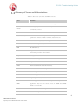
F5 SDC Troubleshooting Guide Glossary of Terms and Abbreviations Table 2: Glossary of Terms and Abbreviations Term Definition AAA Authentication, Authorization and Accounting. Cluster SDC’s group of nodes used to provide translation and connectivity services. CPF Control Plane Function Data Dictionary Defines the format of a protocol’s message and its validation parameters: structure, number of fields, data format, etc.
F5 SDC Troubleshooting Guide Term Definition Physical or virtual addressable entity. A Client or Server Peer in Peer the NGN network that provides or consumes AAA services. Pool A group of Server Peers. RADIUS Remote Authentication Dial In User Service SDC Signaling Delivery Controller SNMP Simple Network Management Protocol SS7 Signaling System No. 7 TCP Transmission Control Protocol TLS Transport Layer Security UDP User Datagram Protocol URI Universal Resource Identification.
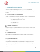
F5 SDC Troubleshooting Guide 2 Troubleshooting Basics This section describes recommended best practices to avoid errors and to help with troubleshooting when they do occur. To resolve specific issues, refer to the relevant chapter in this guide. Referencing the SDC Documentation The SDC product documentation provides a comprehensive overview of system functionality.
F5 SDC Troubleshooting Guide After receiving the script, follow the below procedure to run it: 1. Copy the script file to: /opt/traffix/sdc/bin. 2. Login to the first server and change directory to: /opt/traffix/sdc/bin. 3. Run the following commands: - chmod +x tta_log_collector_v.sh - ./tta_log_collector_v.sh snapshot 4. The script creates a .tar.gz archive that should be copied off the server from /opt/traffix/sdc/output. 5. Repeat steps 2-4 for each of the SDC servers.
F5 SDC Troubleshooting Guide 3 IP Connectivity This section describes troubleshooting issues and solutions relating to IP connectivity. Failed to Activate SCTP Associations 3.1.1 Error Description Dialogic application (gctload) tries to activate a SCTP association and then a M3UA layer using system.txt and config.txt files. If these files were not configured correctly, the assertions of SCTP are left in a Not Active state and then the heart bit messages of M3UA are not sent. 3.1.
F5 SDC Troubleshooting Guide Configure system.txt using native SCTP (Refer to relevant documentation, for example: U10SSS-SwEnv-PM.pdf). Get license from dialogic per specific server and put it in the /opt/DSI directory Verify that the right parameters (based on customer’s configuration) are configured in the config.txt file according to the relevant documentation (U10SSS-SwEnv-PM.pdf). Test SNSLI command. It should be configured as a SCTP client.
F5 SDC Troubleshooting Guide 4 SDC Cluster To achieve maximum availability for cluster resources by detecting and recovering from node and resource-level failures, SDC uses Pacemaker, as its cluster resource manager, and Corosync, as its group communication layer for Pacemaker. For more information about Pacemaker and Corosync, refer to the following link: http://clusterlabs.org/doc/en-US/Pacemaker/1.
F5 SDC Troubleshooting Guide Restart single resource crm resource restart traffix_webui-grp Stop all cluster resource crm configure property stop-all-resources=true Un-stop all cluster resources crm configure property stop-all-resources=false Migrate Web UI to a node (and lock crm resource migrate traffix_webui-grp sdclab001-02 it to stay there) Remove lock forcing Web UI to run crm resource unmigrate traffix_webui-grp on particular node Relay migration of CPF VIP and crm resource migrate traffi
F5 SDC Troubleshooting Guide # crm_mon -nf1 <...skip...> Migration summary: * Node sdclab002-01: traffix_cpf-app-prim:1: migration-threshold=3 fail-count=2 lastfailure='Sun Aug 14 11:12:11 2011' * Node sdclab002-09 4.3.2 Resolution – Current Failure Count You can manually clear the resource failure count with either of the following crm commands: crm resource failcount traffix_cpf-app-prim delete sdclab001-01 crm resource cleanup traffix_cpf-app-clone sdclab001-01 4.3.
F5 SDC Troubleshooting Guide scripting errors. configuration manager. Cause – Scripting Errors One of the initialization/engineering/health monitoring scripts has errors, causing the SPF to crash. Resolution – Verifying Scripts You need to correct the faulty script. Note: Usually you can access the scripts (SDC Life Cycle; Health Monitoring, Engineering) from the Web UI. However, because FEP/CPF are not running, they cannot accept any configuration changes To correct the scripts: 1.
F5 SDC Troubleshooting Guide Check that the problem is related to the config manager For more information, contact F5 Technical Support. 4.4.2 CPF Appears Offline Symptom SDC component appears offline or does not appear at all in the Topology section of the Web UI. Resolution Refer to Section 4.4.1.3 Cause – Configuration Manager or 8.1. EMS Config Manager Fails to Start. FEP Connectivity 4.5.
F5 SDC Troubleshooting Guide - FlowManagerMgmt/Administration/PostSystemInit - FlowManagerMgmt/Administration/StatusCheck/Condition+CheckStatus Cause – Configuration Manager The SDC component (FEP) is unable to retrieve its configurations from the config manager. By default, the connection between each SDC component and the config manager is done using a multicast auto discovery mechanism.
F5 SDC Troubleshooting Guide The Linux command netstat –anp | grep , does not return the LISTEN answer as it should and instead only the prompt line displays. The following is an example of a return LISTEN answer: tcp 0 0 :::8080 :::* tcp 0 0 ::ffff:10.2.108.
F5 SDC Troubleshooting Guide Resolution Make sure that the client’s message timeout is not too short. If using JMeter you can find it inside the element “Diameter Peer Configuration” in “Message Timeout (ms)”. Make sure the client waits until it receives CEA before it sends its first request. If using JMeter, do the following steps: a) Select Thread Group of the scenario. b) Right-click and select: Add, and then Sampler, and then Test Action.
F5 SDC Troubleshooting Guide Resolution Use the installer to properly install SDC. FEP-CPF Communication 4.6.1 CPF Cannot Communicate with FEP Error Description Channels are constantly opened by FEP toward CPF, but CPF rejects them. Causes The FEP’s configuration for minimum channels toward CPF is greater than the corresponding configuration of CPF for maximum channels. This causes the FEP to connect to CPF more channels than CPF allows, so CPF rejects them.
F5 SDC Troubleshooting Guide 4.6.2 CPF Cannot Return Answer Back to FEP Error Description Request is routed correctly to server and answer is returned from server to FEP-O and to CPF, but is not forwarded from CPF back to FEP. Causes The connection between CPF to FEP is disconnected, possibly because one of them did not answer watchdog requests. This might happen when the system is overloaded with too much traffic or too busy with processes running on the machine, or when using a VM.
F5 SDC Troubleshooting Guide The Web UI login page does not load The Web UI rejects the user credentials even when they are right 4.7.2 Causes The server is running out of memory You are trying to connect to the wrong port The Web UI is failing to communicate with the Configuration Manager The Configuration Manager is failing to communicate with the CPF 4.7.
F5 SDC Troubleshooting Guide 5 SDC Pipeline Licensing and Access Control Remote client peer fails to open a link to the SDC. 4.4.1 Error Description Client peer sends a proper CER to the SDC, but link is not established. 4.4.2 Causes The SDC is configured not to allow connection to unknown peers The remote peer is sending the CER messages to an IP address not licensed by F5 No common application-IDs between client peer to SDC 4.4.
F5 SDC Troubleshooting Guide 5.2.1 Request is Not Routed Using the Routing Rows as Expected Error Description When traffic is sent to SDC, and then a change is made to the routing table (i.e. added new rows, or edited existing rows), and then another request is sent to one of the servers, without it being routed using one of the added routing rows. Causes This is due to session stickiness for pools.
F5 SDC Troubleshooting Guide Causes All pools are in “Out of Service” state (since all peers of each of these pools are in a “Close” state (disabled or not yet connected) or “Out of Service”). At least one pool is in an “Open” state – but all of its peers are overloaded (reached maximum rate limit), and all other pools, if exist, are in “Out of Service” state. Note: A pool will be in “Out of Service” state when at least its “Minimum Number of Peers” (configurable, default is 1) is reached.
F5 SDC Troubleshooting Guide timeout, and since clients usually do not respond to requests, the pending timeout will be invoked and cause another endless cycle of requests that will be sent to the client. Causes A bad “Handle Server Error” script is configured for the routing row that was selected for the request. Resolution In the “Handle Server Error” script, reconfigure the “answerFromServer” parameter for any RemoteNodeEvent.
F5 SDC Troubleshooting Guide Client side request, like ULR, routed through SDC, with Roaming Proxy is enabled. The routing of ULR was successful, but peer profile at the client peer is not configured. - Error Message: “Diameter client peer {some peer name} must have a peer profile for Roaming Proxy full functionality. Routing of future requests from server will fail!” Routing of “Forwarded” message of server side request, such as CLR, when roaming is enabled is failed.
F5 SDC Troubleshooting Guide When CPF loads a diameter dictionary, that has two AVPs defined with the same name, but with different commands or vendor IDs, only the first AVP is saved in the application. 5.3.1.1.2 Causes Using a diameter dictionary in which the AVP name is not unique. 5.3.1.1.3 Symptoms The following section describes the error conditions and their relevant error messages. The diameter dictionary used by CPF contains several AVPs that do not have a unique AVP name.
F5 SDC Troubleshooting Guide To add a message with an application ID according to spec (not 0): Create a message so that the name of this message will be built as concatenation of name and needed interface.
F5 SDC Troubleshooting Guide Error Description CPF fails to parse some diameter AVPs with an internal error due to a thrown InvalidAvpLengthValidationException. The message handling continues but a Wireshark capture shows that the incoming message to SDC and outgoing message from SDC are different (no transformation has occurred).
F5 SDC Troubleshooting Guide Figure 3: Outgoing Message AVPs Causes The cause for the illegal parsed value which then failed the parsing can be due to a buffer offset that was incorrectly incremented while parsing the message. A wrong buffer offset can cause AVPs to be parsed from the wrong index which can cause illegal values to be read. . Such errors in a buffer offset can be caused by a wrong AVP description in the used dictionary.
F5 SDC Troubleshooting Guide Figure 4: Parsing Offset This analysis shows that the error in the offset started when parsing the AVP which came before the “AMBR” AVP which is the “SS-Status” AVP. After debugging the parsing of the “SS-Status” AVP, it was found that this AVP was parsed as a grouped AVP while it did not hold any grouped information.
F5 SDC Troubleshooting Guide 1. Take a Wireshark capture of the failed transaction. 2. Compare the message coming into the SDC to the message coming out of the SDC to see at what step Wireshark could not parse the AVPs. 3. Search for the failed AVP code and length value in the message coming into the SDC at the segments where Wireshark was not able to parse the message coming out of the SDC. 4. Identify the last AVP before the failed AVP from the error log. 5.
F5 SDC Troubleshooting Guide Resolution The transformation rule change is only visible once a new session is initiated and the request from the client is sent as only then the change takes place. 5.3.4 3GPP Destination Realm Normalization Does Not Work Error Description A routed request’s destination realm is not normalized although it was configured. Symptoms The following section describes the error conditions and their relevant error messages.
F5 SDC Troubleshooting Guide 6 Performance HTTP Performance is Degraded 6.1.1 Error Description The TPS of the HTTP routing is much slower than expected. 6.1.2 Causes Keep-alive: server/client peers are not using keep-alive. Number of maximum connections (Max Connections Count Limit (Per Server) configured when adding a Remote Peer) between the HTTP server peer and the server is too small to support the traffic load.
F5 SDC Troubleshooting Guide Note: The default value is 10. Generally there should be 20% more connections between the server peer and server than between the client peer. Verify that the Max Connections Count Limit (Per Client) configuration for the HTTP client peer value is configured to support expected traffic load. The Default connection size is 1024.
F5 SDC Troubleshooting Guide 7 Overload Control Receive/Send Rate Limit is Half Than Expected 7.1.1 Error Description Though you have configured a global message rate limit (Transaction receiving rate limit) or specific peer/profile message rate limits (Message sending rate limit), the TPS data graphs only show about half of the configured amount. 7.1.2 Causes The discrepancy is because each counted message might be a request or a response, while each transaction of TPS is both a request and response. 7.
F5 SDC Troubleshooting Guide 8 EMS EMS Config Manager Fails to Start 8.1.1 Symptoms The config manager shuts down upon initialization. 8.1.2 Resolution The parameter that configures the TCP connections between the EMS and the remote sites is missing from the configuration. To add the missing parameter: 1. Add the following under /opt/traffix/sdc/config/sysconfig/traffix_config_mgr: CONFIG_MGR_REMOTE_NETWORK_URI="static:(failover:(tcp://:61617?wireFormat.
F5 SDC Troubleshooting Guide 1. Use netstat to see which of the connections are in Established mode and which are missing. 2. Make sure the IP address that the EMS is trying to connect to is the correct remote site config manager management IP. Note: All remote sites IP addresses are configured under /opt/traffix/sdc/config/sysconfig/traffix_config_mgr) 3. Check for network/firewall/IP table problems.
F5 SDC Troubleshooting Guide 9 Reporting Splunk is software that gathers, indexes, and arranges data from any application, server, or network device in your IT infrastructure. This data can then be generated into analytical reports with tables, charts, and graphs that are displayed in a Web UI. This section describes commonly found errors with Splunk. Splunk Data is Not Shown in Web UI 9.1.
F5 SDC Troubleshooting Guide Figure 6: Waiting for Splunk Data 9.1.2 Resolution You need to verify that the Splunk components are running correctly. The status of the different Splunk components can be checked by running CLI queries on the machine running the EMS. To do this verification, contact F5 Technical Support.