
Manual

10
SETPOINT VALUE
Enter the desired setpoint value. The decimal point position for the setpoint
and hysteresis values follow the selection set in Module 1.
-9999 to 99999
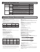
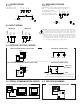
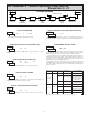
6.4 MODULE 4 - SETPOINT OUTPUT PARAMETERS (4-SPt)
SEL
Setpoint
Action
Setpoint
Select
Setpoint
Value
Output Reset
Action
Hysteresis
Value
Off Time
Delay
On Time
Delay
Output Reset
With Display
Reset Enable
Change Display
Color with
Output State
Backlight
Unit Only
SPSEL
4-SPt
Act-n SPt-n HYS-n tON-n tOF-n rSt-n rEn-n ChC-n
Pro
Standby
Operation
Stb-n brn-n
Probe
Burn-out
PARAMETER MENU
The Setpoint Output Parameters are only active when an optional output
module is installed in the meter.
Enter the setpoint (output) to be programmed. The n in the following
parameters will reflect the chosen setpoint number. After the chosen setpoint
is completely programmed, the display will return to SPSEL. Repeat steps for
each setpoint to be programmed. Select
NO to exit the module. The number of
setpoints available is setpoint output card dependent.
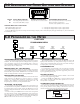
SETPOINT SELECT
SP-2SP-1NO
NO
SPSEL
Select YES to enable Setpoint 2 and access the setup parameters. If NO is
selected, the unit returns to SPSEL and setpoint 2 is disabled.
SETPOINT 2 ENABLE
NOYES
NO
Enb-2
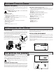
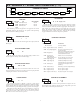
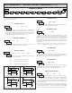
Enter the action for the selected setpoint (output). See Setpoint Output
Figures for a visual detail of each action.
SETPOINT ACTION
HI-Ub
Act-n
100
SPt-n
LO-UbHI-UbLO-bL
HI-bL
LO-Ub
=
HI-Ub
=
LO-bL
=
HI-bL
=
Low Acting, with unbalanced hysteresis
High Acting, with unbalanced hysteresis
Low Acting, with balanced hysteresis
High Acting, with balanced hysteresis
OUTPUT
STATE
OFF
ON
Hys
SP + ½Hys
SP
SP - ½Hys
OFF
TRIGGER POINTS
High Acting (Balanced Hys) = HI-bL
OUTPUT
STATE
OFF
ON
Hys
SP + Hys
SP
OFF
TRIGGER POINTS
Low Acting (Unbalanced Hys) = LO-Ub
OUTPUT
STATE
OFF
ON
Hys
SP + ½Hys
SP
SP - ½Hys
OFF
TRIGGER POINTS
Low Acting (Balanced Hys) = LO-bL
OUTPUT
STATE
OFF
ON
Hys
SP
SP - Hys
OFF
TRIGGER POINTS
High Acting (Unbalanced Hys) = HI-Ub
2
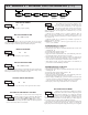
HYS-n
HYSTERESIS VALUE
1 to 59999
Enter desired hysteresis value. See Setpoint Output Figures for visual
explanation of how setpoint output actions (balanced and unbalanced) are
affected by the hysteresis. When the setpoint is a control output, usually
balanced hysteresis is used. For alarm applications, usually unbalanced
hysteresis is used. For unbalanced hysteresis modes, the hysteresis functions on
the low side for high acting setpoints and functions on the high side for low
acting setpoints.
Note: Hysteresis eliminates output chatter at the switch point, while time delay
can be used to prevent false triggering during process transient events.
0.0
tOF-n
0.0
tON-n
OFF TIME DELAY
ON TIME DELAY
OUTPUT RESET ACTION
LAtCHAuto L-dLY
0.0 to 599.9 Sec
0.0 to 599.9 Sec
Enter the time value in seconds that the output is delayed from turning on
after the trigger point is reached. A value of 0.0 allows the meter to update the
output status per the response time listed in the Specifications.
Enter the time value in seconds that the output is delayed from turning off
after the trigger point is reached. A value of 0.0 allows the meter to update the
output status per the response time listed in the Specifications.
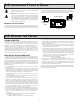
Enter the reset action of the output. See figure for details.
Auto = Automatic action; This action allows the output to automatically reset off
at the trigger points per the Setpoint Action shown in Setpoint Output
Figures. The “on” output may be manually reset (off) immediately by the
front panel RST button or user input.The output remains off until the trigger
point is crossed again.
LAtCH = Latch with immediate reset action; This action latches the output on at
the trigger point per the Setpoint Action shown in Setpoint Output Figures.
Latch means that the output can only be turned off by the front panel
RST
button or user input manual reset, serial reset command or meter power cycle.
Auto
rSt-n