
Manual

3
ADDING OPTION CARDS
The CUB5 meters can be fitted with optional output cards and/or serial
communications cards. The details for the plug-in cards can be reviewed in the
specification section below. The plug-in cards, that are sold separately,
can be
installed initially or at a later date.
WARNING: Disconnect all power to the unit before
installing Plug-in card.
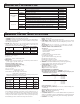
SINGLE RELAY CARD
Type: Single FORM-C relay
Isolation To Sensor & User Input Commons: 1400 Vrms for 1 min.
Working Voltage: 150 Vrms
Contact Rating: 1 amp @ 30 VDC resistive; 0.3 amp @ 125 VAC resistive
Life Expectancy: 100,000 minimum operations
DUAL SINKING OUTPUT CARD
Type: Non-isolated switched DC, N Channel open drain MOSFET
Current Rating: 100 mA max.
V
DS ON
: 0.7 V @ 100 mA
V
DS MAX
: 30 VDC
Offstate Leakage Current: 0.5 mA max.
RS485 SERIAL COMMUNICATIONS CARD
Type: RS485 multi-point balanced interface (non-isolated)
Note: Non-grounded (isolated) RTD probes must be used when multiple units
are connected in an RS485 network, or measurement errors will occur.
Baud Rate: 300 to 38.4k
Data Format: 7/8 bits; odd, even, or no parity
Bus Address: 0 to 99; max 32 meters per line
Transmit Delay: Selectable (refer to CUB5COM bulletin)
RS232 SERIAL COMMUNICATIONS CARD
Type: RS232 half duplex (non-isolated)
Baud Rate: 300 to 38.4k
Data Format: 7/8 bits; odd, even, or no parity
USB PROGRAMMING CARD
Type: USB virtual comms port
Connection: Type B
Baud Rate: 300 to 38.4k
Unit Address: 0 to 99
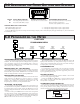
OPTIONAL PLUG-IN CARDS
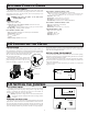
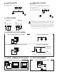
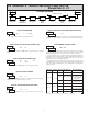
1.0 INSTALLING THE METER
INSTALLATION
The meter meets NEMA 4X/IP65 requirements when properly installed. The
unit is intended to be mounted into an enclosed panel. Prepare the panel cutout
to the dimensions shown. Remove the panel latch from the unit. Slide the panel
gasket over the rear of the unit to the back of the bezel.
The unit should be installed fully assembled. Insert
the unit into the panel cutout.
While holding the unit in place, push the panel
latch over the rear of the unit so that the tabs of the
panel latch engage in the slots on the case. The
panel latch should be engaged in the farthest
forward slot possible. To achieve a proper seal, tighten the latch screws evenly
until the unit is snug in the panel (Torque to approx. 28 to 36 in-oz [0.202 to 0.26
N-m]). Do not over-tighten the screws.
INSTALLATION ENVIRONMENT
The unit should be installed in a location that does not exceed the operating
temperature and provides good air circulation. Placing the unit near devices that
generate excessive heat should be avoided.
The bezel should only be cleaned with a soft cloth and neutral soap product.
Do NOT use solvents. Continuous exposure to direct sunlight may accelerate the
aging process of the bezel.
Do not use tools of any kind (screwdrivers, pens, pencils, etc.) to operate the
keypad of the unit.
2.68
(68 )
+.8
1.30
-.0
(33 )
-.000
+.6
-.0
-.000
+.024
+.025
PANEL
GASKET
BEZEL
PANEL
MOUNTING SCREW
NUT FASTENER
MOUNTING CLIP
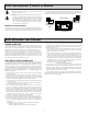
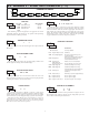
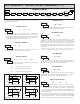
2.0 SETTING THE JUMPERS
INPUT RANGE JUMPER
This jumper is used to select the proper input range. The input range selected
in programming must match the jumper setting. Select a range that is high
enough to accommodate the maximum input signal to avoid overloads. To
access the jumper, remove the rear cover of the meter.
Warning: Exposed line voltage exists on the circuit boards. Remove
all power to the meter and load circuits before accessing inside of
the meter.
REMOVING THE REAR COVER
To remove the rear cover, locate the cover locking tab below the 2nd and 3rd
input terminals. To release the tab, insert a small, flat blade screwdriver between
the tab and the plastic wall below the terminals. Inserting the screwdriver will
provide enough pressure to release the tab locks. To replace the cover, align the
cover with the input terminals and press down until the cover snaps into place.
INPUT RANGE JUMPER
MAIN CIRCUIT
BOARD
10 ohm
INPUT RANGE
JUMPER LOCATION
100 ohm