
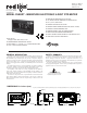
Manual
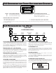

WIRING OVERVIEW
Electrical connections are made via screw-clamp terminals located on the
back of the meter. All conductors should conform to the meter’s voltage and
current ratings. All cabling should conform to appropriate standards of good
installation, local codes and regulations. It is recommended that the power
supplied to the meter (DC or AC) be protected by a fuse or circuit breaker.
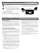
Strip the wire, leaving approximately 0.3" (7.5 mm) bare lead exposed
(stranded wires should be tinned with solder.) Insert the lead under the correct
screw-clamp terminal and tighten until the wire is secure. (Pull wire to verify
tightness.) Each terminal can accept up to one #14 AWG (2.55 mm) wire, two
#18 AWG (1.02 mm), or four #20 AWG (0.61 mm).
EMC INSTALLATION GUIDELINES
Although Red Lion Controls Products are designed with a high degree of
immunity to Electromagnetic Interference (EMI), proper installation and wiring
methods must be followed to ensure compatibility in each application. The type
of the electrical noise, source or coupling method into a unit may be different
for various installations. Cable length, routing, and shield termination are very
important and can mean the difference between a successful or troublesome
installation. Listed are some EMI guidelines for a successful installation in an
industrial environment.
1. A unit should be mounted in a metal enclosure, which is properly connected
to protective earth.
2. Use shielded cables for all Signal and Control inputs. The shield connection
should be made as short as possible. The connection point for the shield
depends somewhat upon the application. Listed below are the recommended
methods of connecting the shield, in order of their effectiveness.
a. Connect the shield to earth ground (protective earth) at one end where the
unit is mounted.
b. Connect the shield to earth ground at both ends of the cable, usually when
the noise source frequency is over 1 MHz.
3. Never run Signal or Control cables in the same conduit or raceway with AC
power lines, conductors, feeding motors, solenoids, SCR controls, and
heaters, etc. The cables should be run through metal conduit that is properly
grounded. This is especially useful in applications where cable runs are long
and portable two-way radios are used in close proximity or if the installation
is near a commercial radio transmitter. Also, Signal or Control cables within
an enclosure should be routed as far away as possible from contactors,
control relays, transformers, and other noisy components.
4. Long cable runs are more susceptible to EMI pickup than short cable runs.
5. In extremely high EMI environments, the use of external EMI suppression
devices such as Ferrite Suppression Cores for signal and control cables is
effective. The following EMI suppression devices (or equivalent) are
recommended:
Fair-Rite part number 0443167251 (RLC part number FCOR0000)
Line Filters for input power cables:
Schaffner # FN2010-1/07 (Red Lion Controls # LFIL0000)
6. To protect relay contacts that control inductive loads and to minimize radiated
and conducted noise (EMI), some type of contact protection network is
normally installed across the load, the contacts or both. The most effective
location is across the load.
a. Using a snubber, which is a resistor-capacitor (RC) network or metal oxide
varistor (MOV) across an AC inductive load is very effective at reducing
EMI and increasing relay contact life.
b. If a DC inductive load (such as a DC relay coil) is controlled by a transistor
switch, care must be taken not to exceed the breakdown voltage of the
transistor when the load is switched. One of the most effective ways is to
place a diode across the inductive load. Most RLC products with solid
state outputs have internal zener diode protection. However external diode
protection at the load is always a good design practice to limit EMI.
Although the use of a snubber or varistor could be used.
RLC part numbers: Snubber: SNUB0000
Varistor: ILS11500 or ILS23000
7. Care should be taken when connecting input and output devices to the
instrument. When a separate input and output common is provided, they
should not be mixed. Therefore a sensor common should NOT be connected
to an output common. This would cause EMI on the sensitive input common,
which could affect the instrument’s operation.
Visit RLC’s web site at http://www.redlion.net/Support/InstallationConsiderations.
html for more information on EMI guidelines, Safety and CE issues as they
relate to Red Lion Controls products.
4.0 WIRING THE METER
4
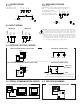
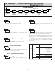
3.0 INSTALLING PLUG-IN CARDS
WARNING: Exposed line voltage exists on the circuit boards.
Remove all power to the meter and load circuits before
accessing inside of the meter.
CAUTION: The Plug-in cards and main circuit board contain static
sensitive components. Before handling the cards, discharge
static charges from your body by touching a grounded bare
metal object. Ideally, handle the cards at a static controlled
clean workstation. Also, only handle the cards by the edges.
Dirt, oil or other contaminants that may contact the cards can
adversely affect circuit operation.
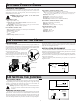
REMOVING THE REAR COVER
To remove the rear cover, locate the cover locking tab below the 2nd and 3rd
input terminals. To release the tab, insert a small, flat blade screwdriver between
the tab and the plastic wall below the terminals. Inserting the screwdriver will
provide enough pressure to release the tab locks. To replace the cover, align the
cover with the input terminals and press down until the cover snaps into place.
The Plug-in cards are separately purchased option cards that perform specific
functions. The cards plug in to the main circuit board of the meter.
Comms or
Programming
Card
Setpoint Card
Range Jumpers
Locking Tab