
Manual

5
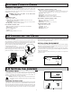
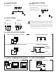
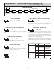
4.1 POWER WIRING
COMM
USR
+9-28 VDC
EXC
INP+
PWR COMMON
+
-
DC Power
+9 to +28 VDC: +VDC
Power Common: -VDC
4.2 USER INPUT WIRING
COMM
USR
+9-28 VDC
EXC
INP+
PWR COMMON
Sinking Logic
USR COMM
USR
The user input of the meter is
internally pulled up to +9 to +28 V
with 10 K resistance. The input is
active when it is pulled low (<0 .7 V).
Connect external switching device between the
User Input terminal and User Input Common.
}
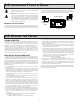
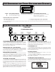
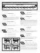
4.3 INPUT WIRING
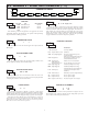
4.4 SETPOINT (OUTPUT) WIRING
4.5 SERIAL COMMUNICATION WIRING
COM
N.C.
N.O.
SINGLE SETPOINT RELAY PLUG-IN CARD
N/C
RS485
2
COMM
A+
B-
N/C
534
N/C
RS232
5
N/C
TX
N/C
43
COMM
COMM
2
RX
61 61
COM
N.O.
N.C.
ELECTRICAL CONNECTIONS
DUAL SETPOINT N-FET OPEN DRAIN PLUG-IN CARD
COM
OSNK 1(2)
(30 V MAX.)
ELECTRICAL CONNECTIONS
OSNK1
OSNK2
COM
3-WIRE RTD
COMM
INP+
EXC
2-WIRE RTD
COMM
INP+
EXC
JUMPER
CAUTION: Power input common and sensor input common are NOT isolated
from user input common. In order to preserve the safety of the meter
application, the power input common and the sensor input common must
be suitably isolated from hazardous live earth referenced voltages; or
input common must be at protective earth ground potential. If not, hazardous
live voltage may be present at the User Inputs and User Input Common
terminals. Appropriate considerations must then be given to the potential of
the user input common with respect to earth common; and the common of
the isolated plug-in cards with respect to input common.
Output Common is not isolated from DC Power Common. Load
must be wired between OSNK terminal and V+ of the load supply.
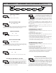
4.6 USB PROGRAMMING
USB PROGRAMING PLUG-IN CARD
SERIAL COMMUNICATIONS PLUG-IN CARD
RJ11 CONNECTOR PIN OUTS