
Manual

Temperature
Scale
Display
Decimal Point
Filter Setting
User Input
Assignment
RTD Type
SEL
tYPE
SCALE
dECPt OFSEt FILtr
bANd
U-ASN
1-INP
Pro
User Input
Function
Display Offset
Value
USrIN
Filter Band
7
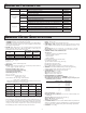
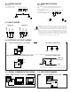
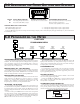
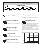
6.1 MODULE 1 - SIGNAL INPUT PARAMETERS (1-INP)
PARAMETER MENU
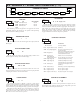
Pt385
tYPE
RTD TYPE
0
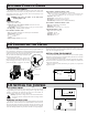
dECPt
0.00
DISPLAY DECIMAL POINT
Select the decimal point location for the desired display resolution. This
selection applies for the Input, MAX and MIN displays.
1
FILtr
FILTER SETTING
If the displayed temperature is difficult to read due to small process
variations or noise, increased levels of filtering will help to stabilize the display.
Software filtering effectively combines a fraction of the current input reading
with a fraction of the previous displayed reading to generate the new display.
Filter values represent no filtering (0), up to heavy filtering (3). A value of 1
for the filter uses 1/4 of the new input and 3/4 of the previous display to
generate the new display. A filter value of 2 uses 1/8 new and 7/8 previous. A
filter value of 3 uses 1/16 new and 15/16 previous.
0,1 2 3
10
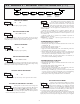
bANd
FILTER BAND
The filter will adapt to variations in the input signal. When the variation
exceeds the input filter band value, the filter disengages. When the variation
becomes less than the band value, the filter engages again. This allows for a
stable readout, but permits the display to settle rapidly after a large process
change. The value of the band is in display units, independent of the Display
Decimal Point position. A band setting of ‘0’ keeps the filter permanently
engaged at the filter level selected in the previous parameter.
00 to 199 display units
Select the RTD type used for the application. The appropriate curve will be
automatically loaded for the selected type. The position of the Input Range
Jumper must match the RTD type selected.
°F
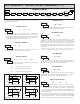
SCALE
TEMPERATURE SCALE
Select the temperature scale. This selection applies for the Input, MAX and
MIN displays.
°C°F
RANGE JUMPERS TYPESELECTION
10 ohmRTD Copper 10
Cu427
100 ohmRTD Nickel 672
Ni672
100 ohmRTD Platinum 392
Pt392
100 ohmRTD Platinum 385
Pt385
0
OFSEt
DISPLAY OFFSET VALUE
The temperature display can be corrected with an offset value. This can be
used to compensate for probe errors, errors due to variances in probe placement
or adjusting the readout to a reference thermometer.
-19999 to 19999
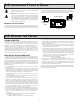
USER INPUT FUNCTION
NO
USrIN
Setpoint 1 and 2 Reset
Setpoint 1 Reset
Setpoint 2 Reset
Print and Reset
Reset both setpoint 1 and 2 outputs.
Resets setpoint 1 output.
Resets setpoint 2 output.
Same as Print Request followed by a
momentary reset of the assigned value(s).
rSt12
rSt-1
rSt-2
P-r5t
Print Request
Serial transmit of the active parameters
selected in the Print Options menu
(Module 5).
Print
Select the value(s) to which the User Input Function is assigned. The User
Input Assignment only applies if a selection of reset, display hold, or print and
reset is selected in the User Input Function menu.
USER INPUT ASSIGNMENT
dSP
U-ASN
dSP
HI-LO
LO
HI
MODE
Reset (Edge triggered)
Program Mode Lock-out
No Function
DESCRIPTIONDISPLAY
Display Select
(Edge Triggered)
Advance once for each activation.
d-SEL
Backlight Color
(Edge Triggered)
Change backlight color with each
activation (backlight version only).
COLOr
Display Intensity Level
(Edge Triggered)
Increase intensity one level for each
activation (backlight version only).
d-LEV
Display Hold
Holds the assigned display, but all other
meter functions continue as long as
activated (maintained action).
Resets the assigned value(s) to the
current input value.
rESEt
d-HLd
See Programming Mode Access chart
(Module 3).
P-Loc
User Input disabled.
NO