
Manual

8
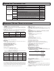
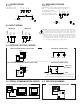
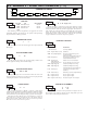
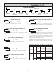
6.2 MODULE 2 - SECONDARY FUNCTION PARAMETERS (2-SEC)
SEL
Max Capture
Delay Time
Max Display
Enable
Min Display
Enable
Access Code
For Service
Operations
Min Capture
Delay TIme
Factory
Service
Operations
2-SEC
HI-En HI-t
LO-En LO-t FCS
CodE
Pro
PARAMETER MENU
MIN DISPLAY ENABLE
YESNO
2.0
HI-t
NO
LO-En
NO
FCS
MAX CAPTURE DELAY TIME
When the Input Display is above the present MAX value for the entered
delay time, the meter will capture that display value as the new MAX reading.
A delay time helps to avoid false captures of sudden short spikes.
2.0
LO-t
MIN CAPTURE DELAY TIME
When the Input Display is below the present MIN value for the entered delay
time, the meter will capture that display value as the new MIN reading. A delay
time helps to avoid false captures of sudden short spikes.
0.0 to 999.9 seconds
NO
HI-En
MAX DISPLAY ENABLE
0.0 to 999.9 seconds
Select YES to perform any of the Factory Service Operations shown below.
FACTORY SERVICE OPERATIONS
yESNO
YESNO
Enables the Maximum Display Capture capability.
Enables the Minimum Display Capture capability.
The CUB5RT uses stored resistance calibration values
to provide accurate temperature measurements. Over
time, the electrical characteristics of the components
inside the meter could slowly change. The result is that
the stored calibration values may no longer accurately
define the input circuit. For most applications, recalibration every 1 to 2 years
should be sufficient.
Calibration of the CUB5RT involves a resistance calibration. Allow 30
minute warm up before performing any calibration related procedure. The
following procedures should be performed at an ambient temperature of 15 to
35 °C (59 to 95 °F).
Calibration should only be performed by individuals experienced in
calibrating electronic equipment.
CAUTION: The accuracy of the calibration equipment will directly affect the
accuracy of the CUB5RT.
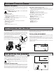
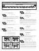
10 OHM RTD Range Calibration
1. Set the Input Range Jumper to 10 ohm.
2. With the display at CodE 48, press and hold the SEL button for 2 seconds. Unit
will display
CAL NO.
3. Press the RST button. Display reads CAL r10.
4. Press the SEL button. Display reads 00r.
5. Apply a direct short to terminals INP+, EXC, and COMM using a three wire
link. Press SEL. Display reads CALC for about 15 seconds.
6. When the display reads
15.0r, apply a precision resistance of 15 ohms (with an
accuracy of 0.01% or better) to terminals INP+, EXC, and COMM using a
three wire link. Press SEL. Display reads CALC for about 15 seconds.
7. When display reads CAL NO, press the SEL button to exit calibration, or
proceed to the 100 ohm RTD Range Claibration.
100 OHM RTD Range Calibration
1. Set the Input Range Jumper to 100 ohm.
2. With the display at CodE 48, press and hold the SEL button for 2 seconds. Unit
will display CAL NO.
3. Press the
RST button until the display reads CAL r100.
4. Press the SEL button. Display reads 0.0r.
5. Apply a direct short to terminals INP+, EXC, and COMM using a three wire
link. Press SEL. Display reads CALC for about 15 seconds.
6. When the display reads
300.0r, apply a precision resistance of 300 ohms (with
an accuracy of 0.01% or better) to terminals INP+, EXC, and COMM using
a three wire link. Press SEL. Display reads CALC for about 15 seconds.
7. When display reads CAL NO, press the SEL button to exit calibration.
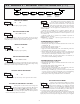
CALIBRATION
48
CodE
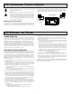
RESTORE FACTORY DEFAULT SETTINGS
Entering Code 66 will overwrite all user settings with
the factory settings. The meter will display rESEt and then
return to
CodE 00. Press SEL button to exit the module.
Pressing both the SEL and the RST button on power-up
will also load the factory settings and display rESEt. This allows operation in
the event of a memory failure or corruted data.
66
CodE
RESISTANCE DISPLAY MODE
Entering Code 85 will place the CUB5RT in a resistance
display mode. This mode is useful for diagnostic purposes
before and after calibration, or to display the measured
resistance of a connected RTD probe. If the RTD type is set
for Cu427 with the jumper set to the 10 ohm position, the display will read
resistance in
0.000 ohms resolution. For all other RTD types, with the jumper in
the 100 ohm position, the display will read in
0.00 ohms resolution.
Re-entering code 85 toggles the display back to the temperature display mode
without having to remove power from the meter. If power is removed, the
display always returns to the temperature display mode when power is reapplied.
85
CodE