
Owner's manual

3
TYPE B
USB
STATUS
USB HOST
STATUS
PORT B
PORT A
COMM
RTS (PIN 6)
Tx
CTS (PIN 1)
Rx
COMM
RTS (PIN 6)
Rx
COMM
Tx
COMM
CTS (PIN 1)
(NIC)
ETHERNET
RxB
TxA (PIN 8)
COMM
TxB
TxEN
TxB (PIN 1)
RxA
TxA
AUXILIARY
ETHERNET
(NIC)
COMMS PORTPGM PORT COMMS PORT
RS232 RS485 RS232
DEVICE
USBPOWER
-
+
USB HOST
PORT A (PGM)
ETHERNET
RS232 RS232
PORT BPORT A
RS485
AUXILIARY
ETHERNET
POWER
CHASSIS
COMMON
+DC VOLTAGE
1
2
3
CONNECTOR
[OPTIONAL]
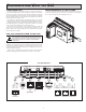
G10 PORT PIN OUTS
CONFIGURING A G10
The G10 is configured using Crimson
®
software. Crimson is available as a
free download from Red Lion’s website. Updates to Crimson for new features
and drivers are posted on the website as they become available. By configuring
the G10 using the latest version of Crimson, you are assured that your unit has
the most up to date feature set. Crimson
®
software can configure the G10 through
the RS232 PGM port, USB port, or SD.
The USB port is connected using a standard USB cable with a Type B
connector. The driver needed to use the USB port will be installed with Crimson.
The RS232 PGM port uses a programming cable made by Red Lion to connect
to the DB9 COM port of your computer. If you choose to make your own cable,
use the “G10 Port Pin Out Diagram” for wiring information.
The SD can be used to program a G10 by placing a configuration file and
firmware on the SD card. The card is then inserted into the target G10 and
powered. Refer to the Crimson literature for more information on the proper
names and locations of the files.
USB, DATA TRANSFERS FROM THE SD CARD
In order to transfer data from the SD card via the USB port, a driver must be
installed on your computer. This driver is installed with Crimson and is located
in the folder C:\Program Files\Red Lion Controls\Crimson 3.0\Device\ after
Crimson is installed. This may have already been accomplished if your G10 was
configured using the USB port.
Once the driver is installed, connect the G10 to your PC with a USB cable,
and follow “Mounting the SD” instructions in the Crimson 3 user manual.
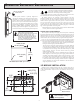
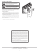
INSERTION/REMOVAL OF THE SD CARD
Insert the SD card into the slot provided with the card oriented as shown. The
card is inserted properly when the end of the card is flush with the Graphite
case. To remove the SD card, push in slightly on the card.
WARNING - DO NOT CONNECT OR DISCONNECT CABLES
WHILE POWER IS APPLIED UNLESS AREA IS KNOWN TO BE
NON-HAZARDOUS. USB PORT IS FOR SYSTEM SET-UP AND
DIAGNOSTICS AND IS NOT INTENDED FOR PERMANENT
CONNECTION.
cOmmunIcatIng WIth the g10