
Owner manual


1
SIMPLE ON-LINE RANGE SETTING
(Using Actual Input Signal or Signal Generator)
USER SETTABLE FULL SCALE FREQUENCY FROM
1 Hz to 25 KHz
FOUR OUTPUT OPERATING RANGES
(0 to 5 V, 0 to 10 V, 0 to 20 mA, and 4 to 20 mA)
PROGRAMMABLE INPUT CIRCUIT ACCEPTS OUTPUTS FROM A
VARIETY OF SENSORS
85 to 250 VAC and 9 to 32 VDC POWERED VERSIONS
AVAILABLE
LOW FREQUENCY CUT-OUT AND OVERRANGE INDICATION
3-WAY ELECTRICAL ISOLATION (POWER/INPUT/OUTPUT)
INPUT AND OUTPUT INDICATION LEDs
MODEL IFMA - DIN-RAIL FREQUENCY TO ANALOG CONVERTER
DESCRIPTION
The Model IFMA accepts a frequency input, and outputs an analog voltage or
current in proportion to the input frequency, with 0.1% accuracy. The full scale
input frequency can be set to any value from 1 Hz to 25 KHz, either with a
frequency source, or digitally with the on-board rotary switch and push-button.
The IFMA utilizes a seven position DIP switch, a rotary switch, a push-button
and two indication LEDs to accomplish input circuit configuration, operational
parameter set-up, and Input/Output indication. The input circuitry is DIP switch
selectable for a variety of sources.
The indication LEDs are used during normal operation to display the input
and output status of the IFMA. These LEDs are also used to provide visual
feedback to the user of the existing parameter settings during parameter set-up.
The IFMA operates in one of four output modes. The programmable minimum
and maximum response times provide optimal response at any input frequency.
The unit is equipped with a universal mounting foot for attachment to
standard DIN style mounting rails, including top hat profile rail according to EN
50 022 - 35 x7.5 and 35 x 15, and G profile rail according to EN 50 035 - G 32.
SAFETY SUMMARY
All safety related regulations, local codes and instructions that appear in the
manual or on equipment must be observed to ensure personal safety and to
prevent damage to either the instrument or equipment connected to it. If
equipment is used in a manner not specified by the manufacturer, the protection
provided by the equipment may be impaired.
SPECIFICATIONS
1. POWER:
AC Operation: 85 to 250 VAC, 48 to 62 Hz; 6.5 VA
DC Operation: 9 to 32 VDC; 2.5 W
Power Up Current: Ip = 600 mA for 50 msec. max.
2. SENSOR POWER: (AC version only) +12 VDC ±25% @ 60 mA max.
3. OPERATING FREQUENCY RANGE:
From 0 Hz to 25 KHz; user selectable.
4. SIGNAL INPUT: DIP switch selectable to accept signals from a variety of
sources, including switch contacts, outputs from CMOS or TTL circuits,
magnetic pickups, and all standard RLC sensors.
Current Sourcing: Internal 1 K pull-down resistor for sensors with current
sourcing output. (Max. sensor output current = 24 mA @ 24 V output.)
Current Sinking: Internal 3.9 K pull-up resistor for sensors with current
sinking output. (Max. sensor current = 3 mA.)
Low Bias: Input trigger levels V
IL
= 0.25 V, V
IH
= 0.75 V; for increased
sensitivity when used with magnetic pickups.
Hi Bias: Input trigger levels V
IL
= 2.5 V, V
IH
= 3.0 V; for logic level signals.
Max. Input Signal: ±90 V; 2.75 mA max. (With both Current Sourcing and
Current Sinking resistors switched off.)
5. SIGNAL VOLTAGE OUTPUT (Selectable):
0 to 5 VDC @ 10 mA max.
0 to 10 VDC @ 10 mA max.
6. SIGNAL CURRENT OUTPUT (Selectable):
0 to 20 mA @ 10 VDC min.
4 to 20 mA@ 10 VDC min.
7. OUTPUT COMPLIANCE:
Voltage: 10 V across a min. 1K load (10 mA). Factory calibrated for loads
greater than 1 M.
Current: 20 mA through a max. 500 load (10 VDC).
8. ACCURACY: ±0.1% of full scale range (±0.2% for 0 to 5 VDC range).
9. RESOLUTION:
Voltage : 3.5 mV min.
Current: 5 μA min.
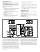
4.20 REF
1.08
3.12
(27.5)
(106.7)
(79.2)
0
9
8
7
6
5
4
3
2
1
M1866G
OUT
IN
IFMA
S
S
T
A
T
U
INSTRUCTIONS, PLEASE REFER
FOR HOOK-UP AND OPERATING
INPUT
COMM
85-250VAC 50/60HZ 6.5VA
RED LION CONTROLS
MADE IN U.S.A.
M1867G
5
FOR SET-UP INSTRUCTIONS.
SEE THE IFMA BULLETIN
TO THE IFMA BULLETIN.
!
YORK, PA.
OUT
AC
~
12
11
98
V-
IN
6
AC
~
60mA
+12VDC
10
7
V+ 4
SINK
SRC.
LOGIC
MODE
CFG2
CFG0
CFG1
ON
IFMA
I-3
2
I+ 1
DIMENSIONS In inches (mm)
CAUTION: Risk of Danger.
Read complete instructions prior to
installation and operation of the unit.
CAUTION: Risk of electric shock.
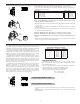
ORDERING INFORMATION
Bulletin No. IFMA-F
Drawing No. LP0340
Released 07/09
Tel +1 (717) 767-6511
Fax +1 (717) 764-0839
www.redlion.net
UL Recognized Component,
File # E137808
MODEL NO.
DESCRIPTION
PART NUMBERS FOR AVAILABLE
SUPPLY VOLTAGES
9 to 32 VDC 85 to 250 VAC
IFMA Pulse Rate to Analog Converter IFMA0035 IFMA0065
For more information on Pricing, Enclosures & Panel Mount Kits refer to the
RLC Catalog or contact your local RLC distributor.