
User guide


1
USER PROGRAMMABLE INPUT
(Thermocouple types J, K, T, & E, or millivolt)
MICROPROCESSOR CONTROLLED
SIMPLE ADJUSTABLE RANGE SETTING (Using Input Signal)
THERMOCOUPLE BREAK DETECTION
MOUNTS ON “T” AND “G” STYLE DIN RAILS
3-WAY ELECTRICAL ISOLATION (POWER/INPUT/OUTPUT)
MULTIPLE ANALOG OUTPUTS (0 to 20 mA, 4 to 20 mA, and 0 to
10 VDC)
WIDE OPERATING TEMPERATURE RANGE (-25°C to 75°C)
POWER & MEMORY ERROR INDICATION
9 to 32 VDC POWERED
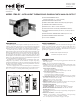
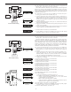
DESCRIPTION
The ITMA accepts a thermocouple or millivolt input and converts it into a
voltage or current output. The voltage or current output is linearly proportional
to the temperature or millivolt input. This output is ideal for interfacing to
indicators, chart recorders, controllers, or other instrumentation equipment.
The ITMA is DC powered. The DC power input is isolated from the signal
input and analog output. The unit scales the analog output proportionally to the
thermocouple or millivolt input signal. The analog output may be configured for
one of the following: 0 to 20 mA, 4 to 20 mA, or 0 to 10 VDC. Making the
signal conversion with the ITMA to a current output signal, makes the signal
less susceptible to noise interference and allows accurate transmission over long
distances. The 3-Way isolation allows the use of grounded thermocouples which
can provide additional noise reduction benefits.
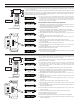
The ITMA uses a ten position DIP switch to accomplish the input sensor
configuration, range selection, and unit calibration. A simple range setting
technique (Field Calibration) is used so the actual input signal adjusts the output
for scaling. This technique eliminates the need for potentiometers which are
vulnerable to changes due to vibration.
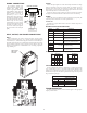
The unit is equipped with a universal mounting foot for attachment to
standard DIN style mounting rails, including top hat rail (T) according to EN 50
022 - 35 × 7.5 and 35 × 15, and (G) profile according to EN 50 035 - G 32.
SAFETY SUMMARY
All safety related regulations, local codes and instructions that appear in the
manual or on equipment must be observed to ensure personal safety and to
prevent damage to either the instrument or equipment connected to it. If
equipment is used in a manner not specified by the manufacturer, the protection
provided by the equipment may be impaired.
SPECIFICATIONS
1. POWER: 9 to 32 VDC; 1.75 W The power supply must have 300 mA for 200
msec. surge capacity.
2. INPUT: J, K, T, E, mV [selectable via DIP switch]
3. OUTPUT: Self-powered (active); All output signals scaled linearly using
temperature or mV input. Unit is shipped set for 4 to 20 mA output. 4 to 20
mA or 0 to 20 mA selected via internal jumper.
Voltage Output Compliance:
0 to 10 VDC across min 1 KΩ load (10 mA)
20 mV peak to peak max. ripple (for frequencies up to 120 Hz)
Current Output Compliance:
0 to 20 mA through max. 600Ω load (12 VDC)
4 to 20 mA through max. 600Ω load (12 VDC)
15 mV peak to peak max. ripple across 600Ω load (for freq. up to 120 Hz)
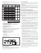
4. TC BREAK DETECTION: Nominal values shown in the following order:
(0 to 20 mA, 4 to 20 mA, and 0 to 10 VDC).
Upscale: 22.9 mA, 22.5 mA, and 11.5 VDC
Downscale: -0.5 mA, 3.5 mA, and -0.4 VDC
5. RESPONSE TIME: 400 msec (to within 99% of final value w/step input;
typically, response is limited to response time of probe.)
6. TEMPERATURE EFFECTS:
Temperature Coefficient: ± 0.025% of input range per °C
Ice Point Compensation: ± 0.75°C for a 50°C change in temperature
7. DIELECTRIC WITHSTAND VOLTAGE: 1500 VAC for 1 minute
Working Voltage: 50 VAC
Power input to Signal input, Power input to Signal output, & Signal input to
Signal output.
8. RANGE & ACCURACY: (12 Bit resolution)
Accuracy: ± ( 0.075% Range + 0.25°C [Conformity] + 0.50°C [Ice Point])
at 23°C after 20 min. warm-up, conforming to ITS-90.
Note: TC Conformity and Ice Point do not apply to mV input
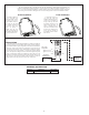
MODEL ITMA DC - INTELLIGENT THERMOCOUPLE MODULE WITH ANALOG OUTPUT
4.20 REF
1.08
3.12
(27.5)
(106.7)
(79.2)
ERROR
POWER
ITMA
OUTPUT CAL
FIELD CAL
BASIC CAL
ICE PT DIS/EN
OPEN SEN UP/DN
RANGE
RANGE
DIP SWITCH SETTINGS:
ON = 1 OFF = 0
MC2220X
8
9
10
TC TYPE
TC TYPE
TC TYPE
4
5
6
7
3
2
1
UP 1
7
0
0
1
1
1
1
2
3
1
RANGE
0
1
9
0
0
0
K
T
MV
E
0
0
1
TC TYPE
J
6
0
0
1
10
0
1
1
0
1
1
8
0
SWITCH
4
0
1
5
0
DISABLED
OPEN SEN
DOWN
ICE POINT
ENABLED
9-32 VDC
ERROR
POWER
VDC+ 10
TC+ 7
V+ 4
I+ 1
VDC-
TC-
1211
98
65 V-
32I-
RED LION CONTROLS
MADE IN U.S.A.YORK, PA.
MODEL ITMA
DIMENSIONS In inches (mm)
CAUTION: Read complete instructions prior
to installation and operation of the unit.
Bulletin No. ITMA3-D
Drawing No. LP0405
Released 06/13
Tel +1 (717) 767-6511
Fax +1 (717) 764-0839
www.redlion.net