
User guide


2
Relative Humidity: Less than 85% RH (non-condensing)
Span: The input span can be set to a min. of 1/8 of the full scale range,
anywhere within that range.
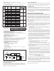
Thermocouple Accuracy for each type and the corresponding ranges:
9. ENVIRONMENTAL CONDITIONS:
Operating Temperature Range: -25°C to 75°C (-13°F to 167°F)
Storage Temperature Range: -40 to 85°C (-40°F to 185°F)
Operating and Storage Humidity: 85% max. relative humidity (non-
condensing) from -25°C to 75°C.
Vibration to IEC 68-2-6: Operational 5-150 Hz, 2 g
Shock to IEC 68-2-27: Operational 30 g
Altitude: Up to 2000 meters
10. MOUNTING: Universal mounting foot for attachment to standard DIN
style mounting rails, including top hat (T) profile rail according to EN50022
-35 × 7.5 and -35 × 15, and G profile rail according to EN50035 - G32.
11. CONNECTION: Compression type terminal block
12. CONSTRUCTION: High impact black plastic case
13. CERTIFICATIONS AND COMPLIANCES:
CE Approved
EN 61326-1 Immunity to Industrial Locations
Emission CISPR 11 Class B
IEC/EN 61010-1
RoHS Compliant
Refer to the EMC Installation Guidelines section of this bulletin for
additional information.
14. WEIGHT: 4.02 oz. (114.0 g)
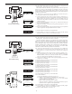
FUNCTION DESCRIPTIONS
Open Sensor Detection
The output can be set to go Upscale or Downscale for the detection of an
open sensor. The nominal values for each output range are listed under TC
Break Detection in the Specifications section. This setting is always active, so
changes to the setting are effective immediately.
Ice Point Compensation
The Ice Point Compensation for the thermocouple sensors can be enabled (DIP
Switch OFF) or disabled (DIP Switch ON). The mV sensor input is not affected
by this setting. Generally, the Ice Point Compensation is always enabled.
Unit Malfunction
If the unit has scaling problems (output remains at -0.5 mA, 3.5 mA, or -0.5
VDC nominal), check the ERROR LED on the front of the unit. An E
2
PROM
problem is indicated when the ERROR LED is on. If the ERROR LED is on,
perform a Basic Calibration followed by a Field Calibration. Turn the power off
for 5 seconds. Turn power on and check if the ERROR LED is on. If the LED
is on, contact the factory.
EMC INSTALLATION GUIDELINES
Although Red Lion Controls Products are designed with a high degree of
immunity to Electromagnetic Interference (EMI), proper installation and wiring
methods must be followed to ensure compatibility in each application. The type
of the electrical noise, source or coupling method into a unit may be different
for various installations. Cable length, routing, and shield termination are very
important and can mean the difference between a successful or troublesome
installation. Listed are some EMI guidelines for a successful installation in an
industrial environment.
1. A unit should be mounted in a metal enclosure, which is properly connected
to protective earth.
2. Use shielded cables for all Signal and Control inputs. The shield connection
should be made as short as possible. The connection point for the shield
depends somewhat upon the application. Listed below are the recommended
methods of connecting the shield, in order of their effectiveness.
a. Connect the shield to earth ground (protective earth) at one end where the
unit is mounted.
b. Connect the shield to earth ground at both ends of the cable, usually when
the noise source frequency is over 1 MHz.
3. Never run Signal or Control cables in the same conduit or raceway with AC
power lines, conductors, feeding motors, solenoids, SCR controls, and
heaters, etc. The cables should be run through metal conduit that is properly
grounded. This is especially useful in applications where cable runs are long
and portable two-way radios are used in close proximity or if the installation
is near a commercial radio transmitter. Also, Signal or Control cables within
an enclosure should be routed as far away as possible from contactors,
control relays, transformers, and other noisy components.
4. Long cable runs are more susceptible to EMI pickup than short cable runs.
5. In extremely high EMI environments, the use of external EMI suppression
devices such as Ferrite Suppression Cores for signal and control cables is
effective. The following EMI suppression devices (or equivalent) are
recommended:
Fair-Rite part number 0443167251 (RLC part number FCOR0000)
Line Filters for input power cables:
Schaffner # FN2010-1/07 (Red Lion Controls # LFIL0000)
6. To protect relay contacts that control inductive loads and to minimize radiated
and conducted noise (EMI), some type of contact protection network is
normally installed across the load, the contacts or both. The most effective
location is across the load.
a. Using a snubber, which is a resistor-capacitor (RC) network or metal oxide
varistor (MOV) across an AC inductive load is very effective at reducing
EMI and increasing relay contact life.
b. If a DC inductive load (such as a DC relay coil) is controlled by a transistor
switch, care must be taken not to exceed the breakdown voltage of the
transistor when the load is switched. One of the most effective ways is to
place a diode across the inductive load. Most RLC products with solid
state outputs have internal zener diode protection. However external diode
protection at the load is always a good design practice to limit EMI.
Although the use of a snubber or varistor could be used.
RLC part numbers: Snubber: SNUB0000
Varistor: ILS11500 or ILS23000
7. Care should be taken when connecting input and output devices to the
instrument. When a separate input and output common is provided, they
should not be mixed. Therefore a sensor common should NOT be connected
to an output common. This would cause EMI on the sensitive input common,
which could affect the instrument’s operation.
Visit RLC’s web site at http://www.redlion.net/Support/InstallationConsiderations.
html for more information on EMI guidelines, Safety and CE issues as they
relate to Red Lion Controls products.
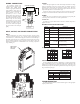
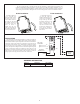
ANALOG
OUTPUT
CIRCUITRY
1
3
CIRCUITRY
CONTROL
PWM
POWER
SUPPLY
22V
3V
CIRCUITRY
PROCESS
CONVERTER
A/D
8
7
1.7V
3V
22M
TC
+
-
CURRENT
OUTPUT
12
10
1.7V
4V
POWER
DC
6
4
+
+
-
-
VOLTAGE
OUTPUT
BLOCK DIAGRAM
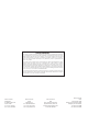
TC
(INPUT)
RANGE
DIP SWITCH
TYPE RANGE
6 7 8 9 10
TEMPERATURE
& mV RANGE
RANGE
ACCURACY
WIRE COLOR
ANSI BS1843
0 1 1 1 0 0 -9 to 6 mV ± 0.0113 mV
N/A
Yellow (+)
Blue (-)
1 1 1 1 0 1 -9 to 22 mV ± 0.0233 mV
Brown (+)
Blue (-)
White (+)
Blue (-)
2 1 1 1 1 0 -9 to 63 mV ± 0.0540 mV
Brown (+)
Blue (-)
mV
3 1 1 1 1 1 -9 to 77 mV ± 0.0645 mV
N/A
0 0 0 0 0 0 -136 to 111°C ± 0.19°C
1 0 0 0 0 1 69 to 575°C ± 0.38°C
2 0 0 0 1 0 338 to 800°C ± 0.35°C
J
3 0 0 0 1 1 -149 to 862°C ± 0.76°C
White (+)
Red (-)
0 0 0 1 0 0 -200 to 541°C ± 0.56°C
1 0 0 1 0 1 427 to 1132°C ± 0.53°C
2 0 0 1 1 0 648 to 1372°C ± 0.54°C
K
3 0 0 1 1 1 -192 to 1372°C ± 1.17°C
Yellow (+)
Red (-)
0 0 1 0 0 0 -225 to 149°C ± 0.28°C
1 0 1 0 0 1 74 to 326°C ± 0.19°C
2 0 1 0 1 0 68 to 400°C ± 0.25°C
T
3 0 1 0 1 1 -200 to 400°C ± 0.45°C
Blue (+)
Red (-)
0 0 1 1 0 0 -111 to 311°C ± 0.32°C
1 0 1 1 0 1 276 to 609°C ± 0.25°C
2 0 1 1 1 0 377 to 1000°C ± 0.47°C
E
3 0 1 1 1 1 -114 to 1000°C ± 0.84°C
Violet (+)
Red (-)
Ice Point Total Error
( ±0.19°C + ±0.25°C + ±0.50°C ) = ±0.94°C
Accuracy Example:
Type “J” Range “0”
-136°C to 111°C
Note: DIP switch settings ON = 1 OFF = 0
ConformityRange