
User Manual


2
DESCRIPTION (Cont’d)
A Legend unit will indicate an overflow condition when the capacity of a
Count display (Process, Batch, or Total) is exceeded, by flashing the word
“OVERFLOW” in the appropriate display.
All count values and program setting are retained when unit power is
removed in nonvolatile memory.
The choice of several reset cycle modes along with the compatibility of count
and control inputs to other RLC products, provides added versatility for stand-
alone and system counter needs.
The rate input uses the time interval method (1/tau) to calculate the rate
value. This method insures high resolution at all input rates. The unit counts
input pulses and after the programmable minimum update time elapses and the
next count edge occurs, the unit will take the number of edges that occurred
during the elapsed time to calculate the rate value. The minimum update time
can be as low as 0.1 second per update, enabling quick response to rate changes.
At slower rates, averaging can be accomplished by programming the Minimum
and Maximum Update Time for the desired response. Extensive scaling
capabilities allow practically any reading at very slow input rates.
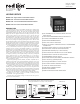
The construction of the Legend series is a light weight high impact plastic
case with a clear viewing window. The sealed front panel with the silicone
rubber keypad meets NEMA 4X/IP65 specifications for wash-down and/or
dusty environments, when properly installed. Plug-in style terminal blocks
simplify installation and wiring change-outs.
SAFETY SUMMARY
All safety related regulations, local codes and instructions that appear in the
manual or on equipment must be observed to ensure personal safety and to
prevent damage to either the instrument or equipment connected to it. If
equipment is used in a manner not specified by the manufacturer, the protection
provided by the equipment may be impaired.
Do not use this unit to directly command motors, valves, or other actuators
not equipped with safeguards. To do so, can be potentially harmful to persons
or equipment in the event of a fault to the unit.
MODELS - LGS & LGD
The single preset unit has one NPN open collector output and the dual preset
unit has two outputs which are activated from presets 1 and 2 respectively. Each
output can be assigned to either Rate or Count display. An optional relay board
can be installed that operates in parallel with the solid state output(s).
MODEL - LGB
The process counter is used to monitor the progress of the count within the
batch. Presets 1 and 2 are assigned to the Process Counter and activate relay
outputs 1 and 2 respectively.
Presets 3 and 4 can be assigned to either the Batch Counter, Totalizer, or Rate
indicator. Presets 3 and 4 activate the NPN open collector outputs O3-SNK and
O4-SNK respectively.
MODEL - LGM
The Multi Preset unit has six Presets (1-6) which control NPN open collector
outputs 01-SNK to 06-SNK respectively. Preset one through four are assigned
to the count display. Presets 5 and 6 can be assigned to either the Rate or Count
display.
SPECIFICATIONS
1. DISPLAY: 2x8, 0.3" (7 mm) high characters, negative image transmissive
LCD, with yellow/green or red LED backlighting.
2. POWER:
AC Operation: 115/230 VAC ±10%, 50/60 Hz, 10 VA, switch selectable.
DC Operation: +12 VDC ±20% @ 250 mA.
3. MEMORY: Non-volatile memory retains all programming information.
Count and Preset values are written to non-volatile memory when power is
interrupted. All other programming parameters are written to memory when
programming mode is exited. If power is removed while in the programming
menus, the parameters are restored to previously saved settings.
Data Retention: 10 years minimum
4. SENSOR POWER: +12 VDC ±25% @ 100 mA.
5. INPUTS A and B: DIP Switch selectable to accept count pulses from a
variety of sources including switch contacts, outputs from CMOS or TTL
circuits, and all standard RLC sensors.
LOGIC: Input trigger levels V
IL
= 1.5 V
MAX
; V
IH
= 3.75 V
MIN
.
Current sinking: Internal 7.8 KΩ pulled up internally to +12 VDC,
I
MAX
= 1.6 mA.
Current sourcing: Internal 3.9 KΩ pull-down, 7.3 mA @ 28 VDC
MAX
.
Debounce: Damping capacitor provided for switch contact bounce.
Limits count speed to 50 Hz and input pulse widths to 10 msec min.
MAGNETIC PICKUP:
Sensitivity: 200 mV peak.
Hysteresis: 100 mV.
Input impedance: 3.9 KΩ @ 60 Hz.
Maximum input voltage: ±50 Vp
Note: For magnetic pickup input, the sink/source DIP switch must be in
the SRC position.
6. RATE ACCURACY: ±0.01%
7. RATE MINIMUM INPUT FREQUENCY: 0.01 Hz.
8. MAXIMUM COUNT RATE IN KHz:
MODEL CNT + DIR QUAD ADD/ADD ADD/SUB
X1 X2 X1 X2 X4 X1* X1*
LGS (Single Preset) 23 11 9 7 5.5 23 12
LGD (Dual Preset) 20 10 8.5 7 5 20 10
LGB (Batch) 17 8 7 7 4 17 9
LGM (Six Preset) 15 7 7 7 3 15 8
Notes:
1. Maximum count rates given are for Process counter set for Auto reset with
the auto cycle preset set to an equivalent of 100 count pulses or greater.
With auto cycle presets less than 100 count pulses, with Count SF =
0.5000 and Count Scale Multiplier = X1, would be 50.
2. Maximum count rate given for X2 & X4 count modes are given for 50%
duty cycle signals and Quad signals with 90
o
phase shift.
*Inputs A & B count rates summed.
9. CONTROL INPUTS:
Programmable user inputs (3): Internal 10 KΩ pull-up to +5 VDC,
V
IL
= 1.0 V
MAX
; V
IH
= 4.0 V
MIN
, response time = 10 msec.
Inhibit: Internal 10 KΩ pull-up to +5 VDC, V
IL
= 1.0
MAX
; V
IH
= 4.0 V
MIN
.
10. SERIAL COMMUNICATIONS:
Type: RS-485 Multi-point Balanced Interface (2 Wire).
(Can connect up to 32 units on a single pair of wires)
Baud Rate: Programmable from 1200 to 9600.
Maximum Addresses: Programmable from 00 to 99.
(Actual number on a single pair of wires is limited by serial hardware
specifications)
Transmit Delay: Programmable for 0.002 or 0.100 second.
Data Format: 10 Bit Frame; 1 start bit, 7 data bits, 1 parity bit, and 1 stop
bit. Parity is programmable for either ODD, EVEN, or No Parity.
11. OUTPUT(S):
Solid-State: Current sinking NPN open collector transistor.
V
CE
= 1V
SAT
@ 100 mA max. V
OH
= 30 VDC max.
(Internal Zener Diode Protection).
Relay(s): Mounted on field-replaceable P.C. board. Form C contacts rated at
5 amps @ 120 VAC/240 VAC or 28 VDC (resistive load), 1/8 H.P. @ 120
VAC (inductive load). The operate time is 5 msec nominal and the release
time is 3 msec nominal.
Programmable Timed Output(s): Programmable time ranges from 0.01 to
99.99 seconds, ±0.05% - 11 msec max.
12. ENVIRONMENTAL CONDITIONS:
Operating Temperature: 0 to 50°C
Storage Temperature: -40 to 70°C
Operating and Storage Humidity: 85% max. (non-condensing) from 0°C
to 50°C.
Vibration to IEC 68-2-6: 5 to 150 Hz, 2 g.
Shock to IEC 68-2-27: Operational 20 g (10 g relay).
Altitude: Up to 2000 meters
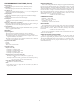
13. CONSTRUCTION: High impact plastic case with clear viewing window.
The front panel meets NEMA 4X/IP65 requirements for indoor use when
installed properly. Installation Category II, Pollution Degree 2. Panel gasket
and mounting clips included.
14. WEIGHT: 1.5 lbs. (0.68 Kg)
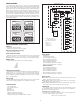
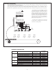
AVAILABLE INDICATION DISPLAYS AND PRESETS FOR EACH MODEL
LGS LGD LGB LGM
RATE
PEAK
VALLEY
COUNT
(1 Preset)
RATE
PEAK
VALLEY
COUNT
(2 Presets)
RATE
PEAK
VALLEY
COUNT
(6 Presets)
RATE
PEAK
VALLEY
PROCESS
BATCH
TOTAL
(4 Presets)
CAUTION: Risk of Danger.
Read complete instructions prior to
installation and operation of the unit.
CAUTION: Risk of electric shock.