
User Manual


8
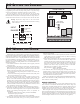
5.3 Module 3 - dIsplay and Front panel Button
paraMeters (3-dSP)
PAR
Front Panel
Display
Select Enable
Display
Update Time
Front Panel
Reset Enable
Programming
Security Code
Zero Display
W/Display
Reset
Display
Intensity
Level
Display
Scroll
Enable
Units Label
Backlight
PARAMETER MENU
1
dSP-t
DISPLAY UPDATE TIME
This parameter sets the display update time in seconds.
1
0.5
2
seconds
The yES selection allows the SEL button to toggle through the enabled
displays.
FRONT PANEL DISPLAY SELECT ENABLE (SEL)
yES
SEL
yES NO
This parameter enables the RST button or user input to zero the input display
value, causing the display reading to be offset.
Note: For this parameter to operate, the RST button or User Input being used
must be set to dSP and the Input value must be displayed. If these conditions are
not met, the display will not zero.
ZERO DISPLAY WITH DISPLAY RESET
NO
ZErO
yES NO
The yES selection allows the display to automatically scroll through the
enabled displays. The scroll rate is every 4 seconds. This parameter only appears
when the MAX or MIN displays are enabled.
DISPLAY SCROLL ENABLE
NO
ScroL
yES NO
Enter the desired Display Intensity Level (1-3). The display will actively dim
or brighten as levels are changed.
DISPLAY INTENSITY LEVEL
1 to 3
3
d-LEV
This selection allows the RST button to reset the selected value(s).
FRONT PANEL RESET ENABLE (RST)
dSP
rSt
HI-LO
LO
HI
NO dSP
OFF
b-LIt
UNITS LABEL BACKLIGHT*
The Units Label Kit Accessory contains a sheet of custom unit overlays
which can be installed in to the meter’s bezel display assembly. The backlight
for these custom units is activated by this parameter.
ON OFF
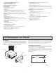
Current Calibration
1. Connect the negative lead of a precision DC current source with an accuracy
of 0.01% or better to the COMM terminal. Leave the positive lead of the DC
current source unconnected.
2. With the display at CodE 48, press the PAR button. Unit will display CAL
NO
3. Press the RST button to select the range to be calibrated.
4. Press the PAR button. Display reads 0.0A
5. With the positive lead of the DC current source unconnected, press PAR.
Display reads CALC for about 8 seconds.
6. When the display reads the selected range, connect the positive lead of the
DC
current source to the current input and apply full-scale input signal for the
range. (Note: For 200 mA range, apply 100 mA as indicated on the display.)
Press PAR. Display reads CALC for about 8 seconds.
7. Repeat steps 3 through 6 for each input range to be calibrated. When display
reads CAL NO, press the PAR button to exit calibration.
Voltage Calibration
1. Connect a precision DC voltage source with an accuracy of 0.01% or better
to the volt input and COMM terminals of the PAXLA. Set the output of the
voltage source to zero.
2. With the display at CodE 48, press the PAR button. Unit will display CAL NO.
3. Press the RST button to select the range to be calibrated.
4. Press the PAR button. Display reads 0.0v.
5. With the voltage source set to zero (or a dead short applied to the input), press
PAR. Display reads CALC for about 8 seconds.
6. When the display reads the selected range, apply full-scale input signal for
the range. (Note: For 200V range, apply 100V as indicated on the display.)
Press PAR. Display reads CALC for about 8 seconds.
7. Repeat steps 3 through 6 for each input range to be calibrated. When display
reads CAL NO, press the PAR button to exit calibration