EN ENGLISH SHALLOW WELL JET PUMP RL-SWJ Series Owner’s Manual THIS PUMP IS DUAL VOLTAGE AND FACTORY SET FOR 230 VOLTS. SEE VOLTAGE SETTING INSTRUCTIONS TO SET FOR 115 VOLTS. Table of Contents www.RedLionProducts.com Before Getting Started.................................................................. 2 Installation Checklist..................................................................... 3 Introduction....................................................................................
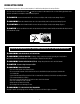
BEFORE GETTING STARTED Read and follow safety instructions. Refer to product data plate(s) for additional operating instructions and specifications. This is the safety alert symbol. When you see this symbol on your pump or in this manual, look for one of the following signal words and be alert to the potential for personal injury or property damage if ignored: ! DANGER warns about hazards that will cause serious personal injury, death or major property damage if ignored.
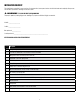
INSTALLATION CHECKLIST This checklist has been provided for your convenience. If a step was missed, ensure power has been shut off at the breaker and completely relieve pressure from the water system before continuing to work on the system. ! WARNING s 75 PSI PRESSURE RELIEF VALVE RECOMMENDED This pump is capable of producing high pressure. Installing a 75 psi pressure relief valve is highly recommended.
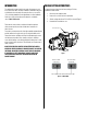
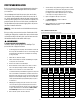
INTRODUCTION VOLTAGE SETTING INSTRUCTIONS The shallow well jet pump is ideal for the supply of fresh water to rural homes, farms, and cabins. This pump is suitable for installations where the vertical distance from the pump to the water level does not exceed 25 ft (7.6 m), including drawdown (less at high altitudes). In offset installation, friction losses in the suction pipe must be taken into consideration (refer to Table 1, Friction Loss).
MATERIALS AND TOOLS NEEDED IMPORTANT INFORMATION MATERIALS NEEDED JOINING PIPE FITTINGS Follow the fitting guidelines below for all attachments unless otherwise specified.
QUICK INSTALLATION GUIDE (Replacing an Existing Pump) This quick installation guide assumes you will be cutting the existing pump free from the plumbing. More detailed instructions are provided in the Detailed Installation Instructions. ! WARNING s 1. DO NOT RUN THE PUMP BEFORE PRIMING IT; THE SEAL AND IMPELLER COULD BE PERMANENTLY DAMAGED 9. Seal the threads of the discharge opening on the pump with PTFE tape or thread compound and insert the 1" male PVC adapter into the discharge opening.
DETAILED INSTALLATION INSTRUCTIONS ! WARNING s DO NOT RUN THE PUMP BEFORE PRIMING IT; THE SEAL AND IMPELLER COULD BE PERMANENTLY DAMAGED Before proceeding, ensure power has been shut off at the breaker. If this is replacing an existing pump, completely relieve pressure from the water system before working on the water system. Open the faucet nearest the tank and allow the water to drain until the tank is empty. SHALLOW WELL APPLICATION 5. Attach the end of the pipe securely to a 1-1/4" PVC 90° elbow.
DETAILED INSTALLATION INSTRUCTIONS DRIVEN WELL (with check valve and well point) 8. A pressure gauge is not supplied with the pump. It should be installed into the 1/8" NPT hole on the front of the casing on the opposite side of the pressure switch (see Typical Installations Figure 5). 1. Drive the well point into the ground according to the instructions that come with the well point. It must be deep enough to bore through the water bearing formation below the water table but should not exceed 25 ft (7.
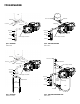
TYPICAL INSTALLATIONS Tank Service Line Relief Valve Service Line Tank Relief Valve Priming Plug Priming Plug Drain Suction Pipe Suction Pipe Vent Pipe Well Seal Well Vent Pipe Well Seal Well Drain Plug Pressure gauge port (1/8" NPT) Drain Plug Pressure Gauge Port (1/8" NPT) Foot Valve Foot Valve Figure 3 - SHALLOW WELL (with foot valve) Figure 4 - SHALLOW WELL, INLINE TANK (with foot valve) Tank Relief valve Service Line Shutoff Valve Priming plug Service line Drain Inline check valve
PUMP TO TANK INSTALLATION 9. Red Lion® recommends using pre-charged diaphragm tanks. Instructions for connecting the pump to a diaphragm tank have been provided for your convenience. If a non-diaphragm tank is used in the pressure system, an air volume control must be used to maintain an air cushion in the pressure tank. If not, air in the tank will gradually be absorbed by water, causing the tank to water log and the pump to short cycle (turn off and on frequently).
WIRING INSTRUCTIONS ! WARNING s ELECTRICAL PRECAUTIONS All wiring, electrical connections, and system grounding must comply with the National Electrical Code (NEC) and with any local codes and ordinances. Employ a licensed electrician. ! WARNING s RISK OF ELECTRICAL SHOCK Before servicing motor-operated equipment, shut off the power at the main electrical panel and disconnect the power supply from motor and accessories. Use safe working practices during servicing of equipment.
PRIMING THE PUMP ! WARNING s DO NOT RUN THE PUMP BEFORE PRIMING IT; THE SEAL AND IMPELLER COULD BE PERMANENTLY DAMAGED. NOTE: You will need enough water to fill the suction line(s) and casing. Priming time depends on the distance from the water source to the pump (5-15 minutes). USING AN INLINE CHECK VALVE USING A FOOT VALVE 1. Open the discharge valve on service line and nearby tap to monitor water flow. 1. Open the discharge valve on the service line and nearby tap to monitor water flow. 2.
MAINTENANCE ! WARNING s RISK OF ELECTRICAL SHOCK Before servicing motor-operated equipment, shut off the power at the main electrical panel and disconnect the power supply from motor and accessories. Use safe working practices during servicing of equipment. PERFORM INSPECTIONS MONTHLY REPLACING MECHANICAL SEAL (See Figure 8) 1. Ensure pump is still securely bolted to the foundation. ! CAUTION ONLY DULY QUALIFIED PERSONS SHOULD PERFORM s 2.
4. Lubricate the rubber components of the rotating seal (9) (soapy water) and slip it on to the shaft with the ‘carbon’ ring towards the ceramic seat.Replace the impeller (6) and the diffuser (4). 4 8 9 5 ! CAUTION Care must be taken not to s contaminate the ceramic seal face. 5. Replace the impeller (4) and the shroud with fasteners. Lubricate and replace the O-ring. 6. Replace the casing (2), making sure that O-ring is not damaged and is in place. 7. Replace drain and fill plugs. 1 4 8.
REPLACEMENT PARTS A12 A13 A3 A8 A7 A6 A5 A10 A9 A11 A14 A4 A3 A15 A1 A2 B11 B10 C3 B12 C4 B6 B1 B2 B7 B9 B14 B5 B13 B8 B1 B1 B3 B4 Contents Item Replacement Parts Where Used A5 & A10 305585001 Case/Seal Plate RL-SWJ50 & RL-SWJ75 A2, A3, A4 & A9 305585002 Hardware Kit RL-SWJ50 & RL-SWJ75 A6, A7 & A8 305585005 Overhaul Kit RL-SWJ50 A6, A7 & A8 305585006 Overhaul Kit RL-SWJ75 A7 305585008 Impeller Kit RL-SWJ50 A7 305585009 Impeller Kit RL-SWJ75 A8 3055
LIMITED WARRANTY For warranty consideration, the Red Lion® Brand (hereafter “the Brand”) warrants that the products specified in this warranty are free from defects in material or workmanship of the Brand. During the time periods and subject to the terms and conditions hereinafter set forth, the Brand will repair or replace to the original user or consumer any portion of this product which proves defective due to materials or workmanship of the Brand.
FR FRANÇAIS POMPE À JET POUR PUITS PEU PROFOND Série de RL-SWJ Manuel du propriétaire CETTE POMPE BITENSION EST CONFIGURÉE PAR DÉFAUT POUR 230 V. CONSULTEZ LES DIRECTIVES POUR RÉGLER LA TENSION D'ALIMENTATION POUR LA CONFIGURER POUR 115 V. Table des matières www.RedLionProducts.com Avant de commencer.................................................................... 2 Liste de vérification pour l’installation ....................................... 3 Introduction......................................
AVANT DE COMMENCER Consultez et respectez toutes les directives de sécurité. Consultez les plaques signalétiques du produit pour obtenir des directives d’utilisation et des spécifications additionnelles. Ceci est le symbole d’alerte de sécurité.
LISTE DE VÉRIFICATION POUR L'INSTALLATION Cette liste de vérification vous est fournie à des fins de commodité. Si l’une des étapes a été oubliée, assurez-vous de couper préalablement l’alimentation provenant du disjoncteur et évacuez complètement la pression du réseau d’eau avant de poursuivre votre travail sur le système. ! AVERTISSEMENT SOUPAPE DE SÛRETÉ DE 75 PSI RECOMMANDÉE s Cette pompe peut produire une pression élevée. L’installation d’une soupape de sûreté de 75 psi est fortement recommandée.
INTRODUCTION DIRECTIVES POUR RÉGLER LA TENSION D'ALIMENTATION La pompe à jet pour puits peu profond est idéale pour l’alimentation en eau douce des maisons en milieu rural, des fermes et des chalets. Cette pompe est adéquate pour les installations où la distance verticale de la pompe à l’eau ne dépasse pas 7,6 m (25 pi), incluant la hauteur de rabattement (moins en haute altitude).
MATÉRIAUX ET OUTILS REQUIS RENSEIGNEMENTS IMPORTANTS MATÉRIAUX REQUIS ASSEMBLAGE DES RACCORDS DE TUYAUTERIE Suivez les directives ci-dessous pour tous les raccordements, sauf mention contraire.
GUIDE D’INSTALLATION RAPIDE (Remplacement d'une pompe existante) Les directives fournies dans ce Guide d’installation rapide présument que la pompe actuelle sera retirée de la plomberie. Les Instructions d’installation détaillées fournissent de plus amples détails. ! AVERTISSEMENT NE DÉMARREZ PAS LA POMPE AVANT DE L’AMORCER; s LE JOINT D’ÉTANCHÉITÉ ET L’IMPULSEUR POURRAIENT ÊTRE ENDOMMAGÉS. 1. Assurez-vous que l’alimentation a été coupée au niveau du disjoncteur avant d’entreprendre toute opération. 9.
INSTRUCTIONS D’INSTALLATION DÉTAILLÉES ! AVERTISSEMENT NE DÉMARREZ PAS LA POMPE AVANT DE L’AMORCER; s LE JOINT D’ÉTANCHÉITÉ ET L’IMPULSEUR POURRAIENT ÊTRE ENDOMMAGÉS. Avant d’entreprendre toute opération, vérifiez que l’alimentation a été coupée au niveau du disjoncteur principal. Si cette pompe remplace une pompe existante, évacuez complètement la pression du réseau d’eau avant de travailler sur celui-ci.
INSTRUCTIONS D’INSTALLATION DÉTAILLÉES PUITS TUBULAIRE (avec clapet anti-retour et pointe filtrante) 1. Enfoncez la pointe filtrante dans le sol en suivant les instructions qui l’accompagnent. Celle-ci doit être enfoncée assez profondément pour traverser la formation aquifère sous le niveau phréatique, mais cette profondeur ne devrait pas dépasser 25 pi (7,6 m). Une seule pointe filtrante pourrait ne pas fournir la quantité d’eau requise.
INSTALLATIONS TYPIQUES Réservoir Conduite de service Soulagement soupape Conduite de service Réservoir Soulagement soupape Bouchon d'amorçage Bouchon d’amorçage Drain Conduite d’aspiration Conduite d’aspiration Tuyau d’évent Joint de puits Puits Tuyau d’évent Joint de puits Puits Bouchon de vidange Bouchon de vidange Orifice de manomètre (1/8 po NPT) Orifice de manomètre (1/8 po NPT) Clapet de pied Clapet de pied Figure 3 - PUITS PEU PROFOND (avec clapet de pied) Figure 4 - PUITS PEU PROFOND,
INSTALLATION DE LA POMPE AU RÉSERVOIR Le tuyau choisi devrait être suffisamment grand pour que la perte de friction (déterminée au Tableau 1, Diagramme de perte de charge) ne dépasse pas 20 pi (6 m) de charge. Red Lion® recommande l’utilisation de réservoirs préchargés à diaphragme. Les instructions pour raccorder la pompe à un réservoir à diaphragme sont fournies à des fins de commodité.
DIRECTIVES DE CÂBLAGE ! AVERTISSEMENT PRÉCAUTIONS ÉLECTRIQUES s Tous câblage, connexions électriques et mise à la terre des systémes doivent se conformer au Code National d'Electricité (NEC) et aux codes et ordonnances locaux. Employez un électricien autorisé. ! AVERTISSEMENT RISQUE DE CHOC ÉLECTRIQUE s Avant d'entretenir ou de réparer n'importe quel appareil à moteur, vous devez couper le courant au panneau électrique principal et déconnecter le moteur et les accessoires.
AMORÇAGE DE LA POMPE ! AVERTISSEMENT NE DÉMARREZ PAS LA POMPE AVANT DE L’AMORCER; s LE JOINT D’ÉTANCHÉITÉ ET L’IMPULSEUR POURRAIENT ÊTRE ENDOMMAGÉS. Vous aurez besoin d’une quantité d’eau suffisante pour remplir le(s) conduite(s) d’aspiration et le boîtier. Le délai d’amorçage dépend de la distance qui sépare la source d’eau de la pompe (entre 5 et 15 minutes). REMARQUE : UTILISATION D’UN CLAPET ANTI-RETOUR INTÉGRÉ UTILISATION D’UN CLAPET DE PIED 1.
ENTRETIEN ! AVERTISSEMENT RISQUE DE CHOC ÉLECTRIQUE s Avant d'entretenir ou de réparer n'importe quel appareil à moteur, vous devez couper le courant au panneau électrique principal et déconnecter le moteur et les accessoires. Durant ce genre de travaux, il faut toujours travailler prudemment. REMPLACEMENT DU JOINT ÉTANCHE MÉCANIQUE PROCÉDEZ À DES INSPECTIONS SUR UNE BASE MENSUELLE 1. Assurez-vous que la pompe est correctement boulonnée à la fondation. (Voir la Figure 8) 2.
REMARQUE : Si la pompe ne sera pas utilisée avant une semaine ou plus, les composants du joint doivent être insérés à sec (sans lubrification). 3. 4 8 9 5 Remonter le moteur (6) sur l’entretoise. Aligner les languettes de l’entretoise avec la fente au bas du châssis du moteur. 4. Lubrifier les composants en caoutchouc du joint rotatif (9) (eau savonneuse), puis le glisser sur l’arbre avec l’anneau en carbone vers le siège en céramique.
PIÈCES DE RECHANGE A3 A8 A7 A6 A5 A10 A9 A11 A14 A4 A3 A15 A1 A2 B11 B10 C3 B12 C4 B6 B1 B2 B7 B9 B14 B5 B13 B8 B1 B1 B3 B4 Contenus Article Pièces de rechange Où utilisé A5 & A10 305585001 Boîtier/plaque de joint d’étanchéité RL-SWJ50 & RL-SWJ75 A2, A3, A4 & A9 305585002 Trousse de quincaillerie RL-SWJ50 & RL-SWJ75 A6, A7 & A8 305585005 Trousse de révision RL-SWJ50 A6, A7 & A8 305585006 Trousse de révision RL-SWJ75 A7 305585008 Trousse de turbine RL-SWJ50
GARANTIE LIMITÉE Lors des requêtes en garantie, la marque de Red Lion® (ci-après appelé « la Marque ») garantit les produits spécifiés dans cette garantie contre tout défaut de matériaux et de maind’oeuvre. Pendant les périodes couvertes par la garantie et selon les conditions indiquées dans la présente, la Marque réparera ou remplacera toute partie de ce produit présentant une défaillance liée aux matériaux ou à la main-d’oeuvre, et ce uniquement auprès du premier utilisateur ou acheteur.
ES ESPAÑOL BOMBA INYECTORA DE POZO POCO PROFUNDO Serie de RL-SWJ Manual del propietario ESTA BOMBA ES DE DOBLE VOLTAJE Y ESTÁ CONFIGURADA DE FÁBRICA PARA 230 V. VER INSTRUCCIONES DE AJUSTE DE VOLTAJE PARA CONFIGURAR A 115 V. Índice www.RedLionProducts.com Antes de empezar......................................................................... 2 Lista de control de instalación...................................................... 3 Introducción..........................................................
ANTES DE EMPEZAR Lea y siga las instrucciones de seguridad. Consulte las placas de datos del producto para obtener instrucciones de operación y especificaciones adicionales. Este es un símbolo de alerta de seguridad.
LISTA DE CONTROL DE INSTALACIÓN Esta lista de control se brinda para su conveniencia. Si se omitió un paso, asegúrese de haber apagado la alimentación eléctrica en el disyuntor y libere completamente la presión del sistema hidráulico antes de seguir trabajando en el sistema. ! ADVERTENCIA SE RECOMIENDA UNA VÁLVULA DE ALIVIO DE PRESIÓN DE 75 PSI s Esta bomba es capaz de producir una elevada presión. Es muy recomendable que se instale una válvula de alivio de presión de 75 psi. Modelo n.
INTRODUCCIÓN INSTRUCCIONES DE AJUSTE DE VOLTAJE La bomba de chorro para pozo poco profundo es ideal para suministrar agua fresca a hogares rurales, granjas y cabañas. Esta bomba es adecuada para las instalaciones donde la distancia vertical desde la bomba hasta el nivel del agua no es mayor de 25 pies (7.6 m), incluido el descenso de nivel (menos a altitudes mayores).
MATERIALES Y HERRAMIENTAS NECESARIOS INFORMACIÓN IMPORTANTE MATERIALES NECESARIOS CONEXIÓN DE ACOPLAMIENTOS PARA TUBERÍAS Siga las directrices de acoplamiento a continuación para todas las conexiones, a menos que se especifique lo contrario. Juntas de tubería • • • • Un rollo de cinta PTFE. Una lata de cebador de PVC. Una lata de cemento de PVC. Abrazaderas de acero (opcional).
GUÍA DE INSTALACIÓN RÁPIDA (Cómo reemplazar una bomba existente) Esta guía de instalación rápida da por sentado que usted cortará la bomba existente de la plomería. Se ofrecen más instrucciones detalladas en Instrucciones de instalación detalladas. ! ADVERTENCIA NO OPERE LA BOMBA ANTES DE CEBARLA; EL SELLO Y EL IMPULSOR SE PODRÍAN DAÑAR PERMANENTEMENTE. s 1. 9. Selle las roscas de la abertura de descarga de la bomba con cinta PTFE o compuesto para roscas, e inserte el adaptador de PVC macho de 25.
INSTRUCCIONES DE INSTALACIÓN DETALLADAS ! ADVERTENCIA NO OPERE LA BOMBA ANTES DE CEBARLA; EL SELLO Y EL IMPULSOR SE PODRÍAN DAÑAR PERMANENTEMENTE. s Antes de proceder, asegúrese de haber apagado la alimentación eléctrica en el disyuntor. Si reemplaza una bomba existente, libere completamente la presión del sistema hidráulico antes de trabajar en el mismo. Abra la llave cerca del tanque y deje drenar el agua hasta que el tanque esté vacío. APLICACIÓN DE POZO POCO PROFUNDO 5.
INSTRUCCIONES DE INSTALACIÓN DETALLADAS POZO HINCADO (con válvula check y punta de perforación de pozo) 1. Introduzca la punta de perforación de pozo en el suelo de acuerdo con las instrucciones provistas con la punta de perforación de pozo. Debe introducirse a una profundidad suficiente de manera que atraviese la formación acuífera debajo del nivel freático pero sin exceder los 7.6 m (25 pies) de profundidad. Una sola punta de perforación de pozo puede no suministrar la cantidad de agua necesaria.
INSTALACIONES TíPICAS Tanque Línea de servicio Válvula de alivio Línea de servicio Tanque Válvula de alivio Tapón de cebado Tapón de cebado Drenaje Tubería de succión Tubería de succión Tubería de ventilación Sello para pozo Pozo Tubería de ventilación Sello para pozo Pozo Tapón de drenaje Orificio de manómetro (1/8 pulg con rosca NPT) Válvula de pie Válvula de pie Figura 3 - POZO POCO PROFUNDO (con válvula de aspiración) Tapón de drenaje Orificio de manómetro (1/8 pulg con rosca NPT) Figura 4
INSTALACIÓN DE LA BOMBA AL TANQUE La tubería seleccionada debe ser lo suficientemente grande para que la pérdida por fricción (determinada a partir de la Tabla 1, Tabla de pérdida por fricción ) nunca exceda los 6 m (20 pies) de la cabeza. Red Lion® recomienda utilizar tanques de diafragma precargado. Se brindan instrucciones para conectar la bomba a un tanque de diafragma para su conveniencia. 8. Quite la tapa de PVC en la válvula de aire del tanque. 9.
INSTRUCCIONES PARA EL CABLEADO ! ADVERTENCIA PRECAUCIONES ELÉCTRICAS s Todo cableado, conexiones eléctricas y sistemas de contacto a tierra deben cumplir con el Código Eléctrico Nacional (NEC) y con cualquier código y ordenanza local. Contrate los servicios de un electricista con licencia.
CEBADO DE LA BOMBA ! ADVERTENCIA NO OPERE LA BOMBA ANTES DE CEBARLA; EL SELLO Y EL IMPULSOR SE PODRÍAN DAÑAR PERMANENTEMENTE. s NOTA: Necesitará bastante agua para llenar la línea de succión y el revestimiento. El tiempo de cebado depende de la distancia desde la fuente de agua hasta la bomba (de 5 a 15 minutos). USO DE UNA VÁLVULA CHECK EN LÍNEA: USO DE UNA VÁLVULA DE CONTENCIÓN: 1. Abra la válvula de descarga en la línea de servicio y el grifo adyacente para monitorear el flujo de agua. 1.
MAINTENMIENTO ! ADVERTENCIA RIESGO DE DESCARGA ELÉCTRICA s Antes de prestar servicio a un equipo operado a motor, desconecte la electricidad al motor en el panel eléctrico principal y desconecte el suministro eléctrico del motor y los accesorios. Practique reglas de seguridad de trabajo cuando preste servicio al equipo. REALIZAR INSPECCIONES MENSUALES 1. Asegúrese de que la bomba todavía está firmemente atornillada a la base. 2.
NOTA: Si la bomba va a estar fuera de servicio por más 4 de una semana, instale los componentes del sello secos (sin lubricación). 3. 8 9 5 Vuelva a ensamblar el motor (6) con el adaptador. Alinee las lengüetas de la placa del adaptador con la ranura en la parte inferior de la carcasa del motor. 4. Lubrique los componentes de goma del cierre rotatorio (9) (con agua jabonosa) y deslícelo sobre el eje con el anillo de ‘carbono’ hacia el asiento de cerámica.
PIEZAS DE RECAMBIO A3 A8 A7 A6 A5 A10 A9 A11 A14 A4 A3 A15 A1 A2 B11 B10 C3 B12 C4 B6 B1 B2 B7 B9 B14 B5 B13 B8 B1 B1 B3 B4 Contenidos Articulo Piezas de Recambio Donde Utilizado A5 & A10 305585001 Estuche/placa de sellado RL-SWJ50 & RL-SWJ75 A2, A3, A4 & A9 305585002 Kit de tornillería RL-SWJ50 & RL-SWJ75 A6, A7 & A8 305585005 Kit de revisión general RL-SWJ50 A6, A7 & A8 305585006 Kit de revisión general RL-SWJ75 A7 305585008 Kit de impulsor RL-SWJ50 A7
GARANTÍA LIMITADA Para consideraciones de la garantía, la marca de Red Lion® (denominada de ahora en adelante “la Marca”), garantiza que los productos especificados en esta garantía están libres de defectos en los materiales y en la mano de obra de la Marca. Durante el período, y sujeto a los términos estipulados en este documento, la Marca reparará o reemplazará al cliente o usuario original cualquier parte del producto que presente defectos materiales o de fabricación atribuibles a la Marca.