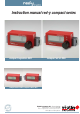
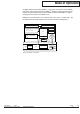
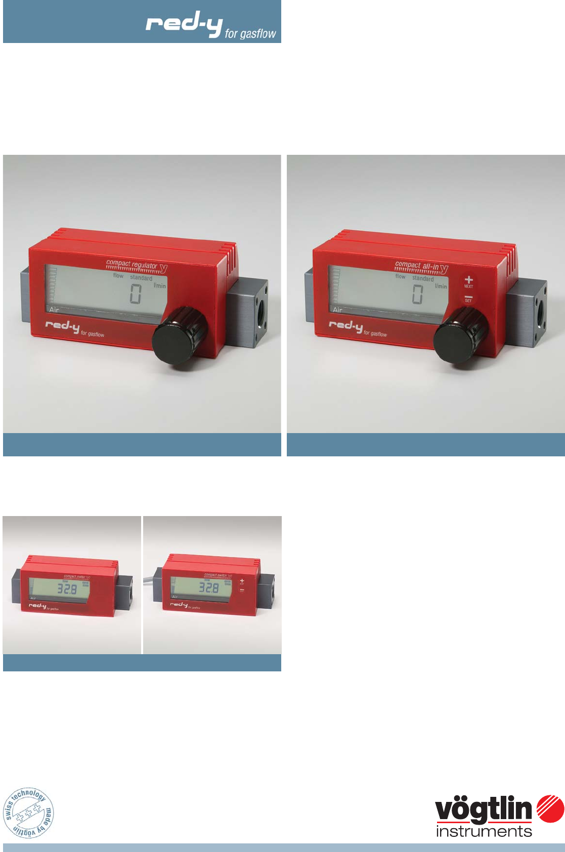
Instruction manual red-y compact series compact regulator GCR compact all-in GCA compact meter GSM & compact switch GCS Vögtlin Instruments AG – flow technology Langenhagstrasse 1 | 4147 Aesch (Switzerland) Phone +41 (0)61 756 63 00 | Fax +41 (0)61 756 63 01 www.voegtlin.com | info@voegtlin.
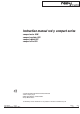
Instruction manual red-y compact series compact meter GCM compact regulator GCR compact switch GCS compact all-in GCA Copyright © 2005 Vögtlin Instruments AG, Switzerland Version: compact_E4_0 Editing: Daniel Walliser, Christian Mahrer Design: Michael Huber You will find up-to-date information on our products on the Internet at www.red-y.
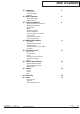
Table of Contents 01 Introduction 4 Operator Benefits Service and Quality Guarantee 02 Mode of Operation 6 Measurement principle CMOS Technology 03 Technical Information 8 General Specifications of the Device Mechanical Specifications Electrical Data Display Measurement Ranges Connector Assignment Conversion Factors for other Gases Loss of Pressure Temperature Compensation Pressure Compensation 04 Mounting & Installation 11 General Tips Installation Position/Location Mechanical Piping Electrical
Introduction 01 Welcome With red-y you get the latest, most modern CMOS sensor technology. CMOSensTM is a technology label and stands for a modern process in which the sensor and the signal processing are combined on a highly integrated chip. This manual will familiarize you with the installation and operation of your red-y. We therefore ask you to read this manual carefully and to contact your sales partner with any questions or doubts.
Introduction Tips and Warnings Before putting the instrument into use, these operating instructions should be read thoroughly. Improper use, errors for lack of understanding and the consequences arising from this, can lead to the destruction of the instrument or even the endangerment of personnel. The equipment should be put into operation and serviced by appropriately qualified personnel only. The proper handling of the products is an absolute requirement for its trouble-free operation.
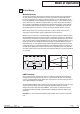
Mode of Operation 02 A bit of theory Measuring principle The measuring principle of thermal flow measurement is perfectly suited for the measurement of gas flows. One of the significant advantages is that the measurement is largely independent of pressure and temperature. By contrast to volumetric principles, pressure and temperature do not have to be additionally measured. Although the principle yields mass as a measurement result (e.g. g/min), most devices are calibrated to standard volumes (e.g. ln/min).
Mode of Operation The digital intelligence linked with the CMOSensTM sensor permits the emission of a fully calibrated, temperature-compensated output signal. The CMOSensTM ‘intelligence’ integrated onto the chip thus facilitates an extremely simple processing of the emitted measurement data. CMOS is a standard technology for the manufacture of integrated circuits. CMOS chips are generally known as ‘semi-conductor chips’, ‘silicon chips’ or ‘computer chips’.
Technical Information 03 Technical Information General Specifications of the Device Accuracy Dynamics Standard measurement range Repeatability Long-term stability Temperature coefficient Pressure coefficient Operating pressure Temperature range Leak rate Heat-up period +/- 1% of full scale 2 – 100 % within the specification Signal suppression less than 2% of full scale +/- 1% from measurement value < 1% from measurement value / year < 0,2% / bar (typical N2) up to 10 bar g 0 – 50 °C 1 x 10⁻⁸ mbars l/s He 3
Technical Information Measurement Ranges Red-y measurement and control devices are supplied with standard measurement ranges for air. As an option, the devices are available with individual measurement ranges and, upon request, can be calibrated with other gases. Standard Measurement Ranges Code Meas. range A4 A5 B4 B5 200 500 2000 5000 Unit mln/min mln/min mln/min mln/min Code Meas.
Technical Information Temperature Compensation Thermal mass flow meters measure the flow of gases to a large extent independent on pressure and temperature. Varying temperatures are automatically compensated by the measurement device. The sensor measures gas temperature and automatically calculates a correction value using a three-dimensional value table. Pressure Compensation With the calibration, the operating pressure specified with the order is also taken into consideration.
Mounting & Installation 04 Mounting & Installation General Tips Check the packet for external damage and contact us immediately in the case of visible damage. Compare the contents of the packet with the delivery slip and check for completeness and technical compliance. This product is a high-precision measuring instrument. We advise you to select the installation site carefully and to follow the instructions and suggestions below.
Mounting & Installation Electrical Connection / Power Supply With the battery-operated devices, mount the battery module. Then the measuring device is ready for use. The useful life of the battery module is about 2 years, but this depends on use. With constantly changing flow rates, the useful life may be shorter. We advise you to use only original battery modules. With the external power supply and alarm options, you receive a connector cable with loose ends. The assignment is printed on the cable.
Operation & Service 05 Operation & Service Heat-Up Time Right when the device is turned on, red-y is ready for use. For the most precise measurements, however, red-y is ready in 30 minutes (option of external feed). Before turning on, please be sure that the wiring is correct and is installed according to the installation plan, and that the gas connections are also mounted in accordance with the installation instructions of the manufacturer.
Operation & Service Battery Replacement If ‘low bat’ appears in the display, we recommend that you change the battery or at least have a new battery module available (Art. Nr. 328-2211). This module can be obtained from your Insentys sales partner. We recommend the following procedure with the replacement of the battery: Changing the battery requires no tools at all. The battery module snaps into two lateral housing clips.
Alarm & Switch Function 06 Alarm & Switch Function Individual Functions in Detail Resetting the Alarm Condition AL CLR In the case of alarm condition, the alarm can be reset. This is only possible if the manual option is selected in the corresponding menu (resetting the alarm AL res). The alarm condition is shown in the display. Setting the Alarm Setpoint ALSETP The desired threshold can be set with the +/- keys. This value can be between 0 and the maximum possible measurement value.
Alarm & Switch Function Diagram of Function Settings Measuring 20.0 one button pressed for 2s both button pressed for 2s Alarm reset no button pressed for 2s al clr no button pressed for 10s adjustable with +/- Alarm Setpoint alsetp SET 1200 no button pressed for 2s 0 - max.
Alarm & Switch Function Alarm situations Situation 1 / Parameters: Function Value Function Value Function Value ALSEtP ALFUNC FAILSA 2.5 AL LO Off DELAY HYST LoSUPr 10s 0.5 On AL rES AUto Hysteresis Setpoint Range Situation 2 / Parameters: Function Value Function Value Function Value ALSEtP ALFUNC FAILSA 2.5 AL HI On DELAY HYST LoSUPr 10s 0.
Totalizer 07 Totalizer General The Totalizer function can be activated by the manufacturer. Function The instrument calculates the integrated value of the gas volume. The added up value is periodically displayed and stored in intervals of 15 minutes in the non-volatile storage (EPROM). In the event of a power disruption, the Totalizer therefore displays the correct total volume. It is, however, possible that the gas volume for the past 15 minutes may be lost.
Dimensions 08 Dimensions Dimensions smart controller G1/4” 14 12,5 25 17 43.3 12,5 A 25.5 x 7 tlet) M4 d ou x 4 n let a 17 (25.5) 69 G1/4 x 12 43.5 25 (in ø19 (12.7) 88.6 12.7 114 Mit externer Speisung / With external power supply / Avec alimentation externe 8.7 (25.5) 69 43.5 25 31.8 25 8.7 B 43.3 3 ø4.8 ø6.8 30 25.5 ø19 (12.7) 12.7 Befestigungsgewinde / Mounting threads / Filets de fixation 15 5.5 Ansicht B / View B / Vue B .5 x5 M4x M4 5.
Dimensions Dimensions smart controller G1/2” 1.3 13 ø4.8 41.8 17.5 35 B 27 53.3 ø6.8 A 7 t) 4 x tle xM ou 27 4 and t le 1.3 G1/2x15 (in G1/2x15 53.5 35 36 88.6 (52.7) 18.
Annex 09 Annex Pressure Loss Pressure Loss mbar Pressure Loss 500 mln/min (Air) 1.6 1.4 1.2 1.0 0.8 0.6 0.4 0.2 0 0 100 200 300 400 500 Flow mln/min Pressure Loss mbar Pressure Loss 5 ln/min (Air) 3.5 3.0 2.5 2.0 1.5 1.0 0.
Annex Pressure Loss Druckverlust Typ200ln/min - 200 ln/min 180 160 Druck (mbarü) Pressure (mbar g) Pressure in mbar Druckverlust in mbar 140 120 100 80 60 40 20 0 0 50 100 150 200 250 Q in ln/min Vögtlin Manual Version red-y compact series compact_E4_0 © Vögtlin Instruments AG Chapter Page 09 22
Annex Type Code Main function G Series gasflow C Function compact series M R S A Measuring Range (Air) Meter Regulator Switch All-in A3 A4 A5 A9 B3 B4 B5 B9 C3 C4 C5 C9 D3 D4 D9 Class 100 mln/min 200 mln/min 500 mln/min Custom range 1'000 mln/min 2'000 mln/min 5'000 mln/min Custom range 10 ln/min 20 ln/min 50 ln/min Custom range 100 ln/min 200 ln/min Custom range S K Materials Materials Valve G1/2", 35x30 Standard, +/-1% of full scale, 1:50 Custom A B S T K Power Supply G1/4", 25x25 Aluminum
Annex Contamination Statement With return of devices, please fill out the following statement completely, especially the reason for the return, the type of residue and cleaning in the case of soiling, as well as indication of hazards. Devices Type Code: Serial number: Reason for the return: Type of contamination Device came in contact with: Cleaned by us with: For the protection of our employees and for general safety during transport, proper cleaning and the use of an appropriate packing are mandatory.