
User guide


11
A
B
C
D
E
A
B
C
D
15°
E
F
2-INSTALLATION INSTRUCTIONS
Technical Dept. - All rights reserved - Reproduction is prohibited
TECHNICAL CHARACTERISTICS
Flues serving a pellet/wood fuelled appliance must meet the following requirements:
• made of materials that are suciently resistant to mechanical stress, heat, the action of the products of combustion and their
vapours.
• made of materials that are impermeable to fumes, condensation, be thermally insulated and resistant to normal mechanical stress
over time
• go in a vertical direction and deviate no more than 45° from the vertical axis and be free of choke points
• be suited to the specic operating conditions of the product and have CE marking (EN1856-1, EN1443).
• Be of the correct size to suit the draft/smoke extraction requirements necessary for the product to work properly (EN13384-1)
• Be suitably caulked externally to avoid condensation and reduce the cooling of the smoke.
• Be at least category T400 (or greater if the appliance requires) and resistant to soot res.
We recommend in particular to check on the data tags of the ue (in accordance with EN1856-1, EN1443) the safety distances that must
be respected in presence of passing combustible materials and the type of insulating material to be used. These indications must be
followed rigorously to avoid serious harm to personnel and surrounding infrastructure.
The chimney opening must be in the same room as the appliance, or at most in the adjoining room, and have a soot and condensation
collection chamber beneath the opening, and be accessible via a watertight metal hatch.
Smoke must be extracted through a single ue (see g. 3) with insulated steel tubes (A) or though an existing ue that complies with
the intended use (B). A simple air shaft in cement must be suitably lined. In either case, ensure to include an inspection cap (AT) and/or
inspection door (AP) and a suitable device for collecting condensation - FIG.1.
It is prohibited to connect more than one wood/pellet or any other type of appliance (vent cowling...) to the same ue.
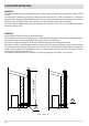
FLAT ROOF
ROOF AT 15°
A = 0.50 metres
B = DISTANCE > 2 metres
C = DISTANCE < 2 metres
D = O.50 metres
E = TECHNICAL VOLUME
A = MIN. 1.00 metres
B = DISTANCE > 1.85 metres
C = DISTANCE < 1.85 metres
D = 0.50 metres above highest
point
E = 0.50 metres
F = REFLUX ZONE
FIGURE 2
FIGURE 3