
User guide


16
T
I
S
I
U
B
A
P
U
I
I
C
4
3
D
2
I
E
V
U
1
F
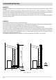
2-INSTALLATION INSTRUCTIONS
EXAMPLES OF CORRECT INSTALLATION
1. Installation of Ø150mm ue with hole for the passage
of the tube increased by:
minimum 100 mm around the tube if next to non
ammable parts such as cement, brick, etc.; or
minimum 300 mm around the tube (or as prescribed by
data tags) if next to ammable parts such as wood etc.
In both cases, install suitable insulation between the ue
and the ceiling.
Always check and respect the data tags on the ue,
in particular the minimum safety distances from
combustible materials.
The previous rules also apply for holes made in walls.
2. Old ue, minimum tube Ø150mm with the inclusion
of an external access door for chimney cleaning.
3. External ue made of insulated stainless steel tubes,
i.e. with double walls minimum Ø150mm: all securely
mounted to the wall. With wind-proof chimney. See g.
7 type A.
4. Ducting system using T joints that allow easy access
for cleaning without having to remove the tubes
FIGURE 11
U = INSULATING
V = ANY REDUCTION FROM 100 TO 80 MM
I = INSPECTION CAP
S = INSPECTION ACCESS PANEL
P = AIR INLET
T = T JOINT WITH INSPECTION CAP
A = MINIMUM 40 MM
B = MAXIMUM 4 M
C = MINIMUM 3°
D = MINIMUM 400 MM
E = HOLE DIAMETER
F = SEE FIG.23456