
Specifications

COPYRIGHT © 2014 RED.COM, INC
RED DSMC OPERATION GUIDE
955-0020_V5.2, REV-C | 128
NOTE: When GENLOCK is selected as the sensor shutter reference, shutter start timing (SHUTTER PHASE) may
still be adjusted. HD-SDI monitor outputs will automatically sync to the external GENLOCK signal as soon as it
is detected, there is no need to enable this function. Sensor shutter sync to GENLOCK is only supported with
HD-SDI.
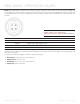
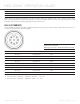
PIN SIGNAL DESCRIPTION
1 GROUND Common Ground
2 SS/GPI Shutter Sync/GPI Trigger Input
3 TIMECODE SMPTE unbalanced timecode Input
4 GENLOCK RS170A Tri-Level Sync Input
The Camera BRAIN’s Shutter Sync/GPI Trigger uses a 3.3 V Schmitt trigger (5 V tolerant). It is not a switch
closure circuit. Therefore, it requires current supplied by the trigger source. Both edges of the input signal may
be used as a trigger.
For example, when GPI trigger is used for Record Start/Stop.
Start Record: On Ground to 3.3 V transition
During Record: Hold at 3.3 V
Stop Record: On 3.3 V to Ground transition
During Stop: Hold at Ground
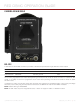
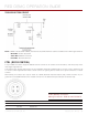
SYNC (Video Sync) Connector
Mating Connector: FGG.00.304.CLAD27Z