
Specifications


RED DSMC OPERATION GUIDE
COPYRIGHT © 2014 RED.COM, INC 955-0020_V5.2, REV-G | 177
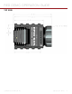
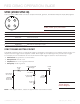
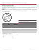
SYNC (VIDEO SYNC IN)
The 4-pin 00B LEMO SYNC connector accepts timecode, genlock, and General Purpose Input (GPI) signals.
1
2
4
3
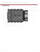
4-PIN 00B LEMO SYNC CONNECTOR
1
PIN SIGNAL DESCRIPTION
1 GROUND Common Ground
2 SS/GPI Shutter Sync/GPI Trigger Input
3 TIMECODE SMPTE unbalanced timecode Input
4 GENLOCK RS170A Tri-Level Sync Input
1. Mating connector: FGG.00.304.CLAD27Z
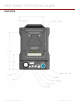
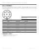
SYNC TRIGGER BUTTON CIRCUIT
The SYNC connector has a 3.3 V Schmitt trigger (5 V tolerant). The trigger is not a switch closure circuit, so it
requires that the trigger source supplies current. Both edges of the input signal may be used as a trigger.
For example, this is the behavior of the circuit when the GPI trigger is used for record start/stop:
Start Record: On ground to 3.3 V transition
During Record: Hold at 3.3 V
Stop Record: On 3.3 V to ground transition
During Stop: Hold at ground
Input Voltage:
3.3 V to 5.0 V
100 ohm
1/4 W
On when output
signal is high
10 uF
electrolytic
6.3 V min.
Female
BNC
Push to make/break
button/toggle
Batteries:
2x AA or AAA
3x AA or AAA
1.7 V, 20 mA
68 ohm
1/4 W
NOTE: In the diagram above, values are approximate. Use standard values.
SYNC (Video Sync) Connector
Trigger Button
Circuit Diagram