
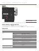
Specifications

COPYRIGHT © 2014 RED.COM, INC
RED DSMC OPERATION GUIDE
955-0020_V5.2, REV-G | 20
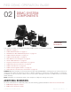
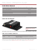
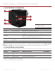
+1 ADAPTOR MODULE CONNECTIONS
1
4
2
5
3
CONNECTOR CONNECTOR TYPE CONNECTOR FUNCTION
Mounting 1/4-20 mounting Supports bolt-on auxiliary equipment
EVF/LCD
1
N/A Custom digital video and power interconnection between BRAIN
and RED EVF or RED LCD; Pinout not published
Auxiliary power
out (PWR)
4-pin 0B LEMO Supplies unregulated (+) 11.5 to 17 V battery pass-through;
Connect to 2-pin LEMO accessories with the RED 4-Pin to 2-Pin
Adaptor Cable; Max sustained current is 2 A
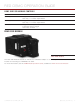
REDMOTE
®
dock
connector
8-point POGO
connector
Power and support for the REDMOTE
Dock connector SEARAY connector Supports power and communication with modules
1. WARNING: DO NOT use the EVF/LCD connector if a Pro I/O Module is connected to the BRAIN.
NOTE: The default auxiliary power output setting is on. To toggle the power setting on/off, go to Menu > Power >
Power Out > +1 PWR. The last power output setting is saved until a firmware upgrade or a factory reset.
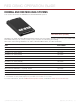
+1 ADAPTOR MODULE ACCESSORIES
For more information, as well as a full list of EVF/LCD cables and other accessory cables, visit www.red.com.
ACCESSORY CONNECTOR TYPE CONNECTOR FUNCTION PART NUMBER
4-Pin To 2-Pin
Adaptor Cable
1
4-pin 0B to 2-pin 0B
LEMO
Power support for 2-pin based accessories 790-0334
Micro HDMI-to-
HDMI Adaptor
2
Micro HDMI to
Standard HDMI
HDMI video connection from BRAIN to support
auxiliary EVF/LCD attachment
N/A
1. The 4-Pin to 2-Pin Adaptor Cable converts 4-pin power into a 2-pin female LEMO connection, enabling support for 2-pin based acces-
sories from the +1 Adaptor Module or Pro I/O Module.
2. The Micro HDMI-to-HDMI Adaptor is field-replaceable.
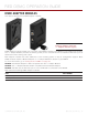
+1 Adaptor Module