USE AND INSTALLATION MANUAL EN PELLET STOVE EDERA MULTIAIR MODEL Translation of original instructions 8901219300
TABLE OF CONTENTS INTRODUCTION...........................................................................................................1 1-WARNINGS AND WARRANTY CONDITIONS..................................................................2 2-INSTALLATION INSTRUCTIONS...................................................................................5 3-INSTALLATION AND ASSEMBLY................................................................................13 4-OPERATION......................................
INTRODUCTION Dear Customer, Thank you for having chosen our product. To allow for optimal operation and for you to enjoy the warmth and sense of wellbeing that the fire can convey in your home, we advise you to read this manual carefully before starting up the product for the first time. REVISIONS TO THE PUBLICATION The content of this manual is strictly technical and property of MCZ Group Spa.
1-WARNINGS AND WARRANTY CONDITIONS SAFETY PRECAUTION • Installation, electrical connection, functional verification and maintenance must only be performed by qualified or authorised personnel. • Install the product in accordance with all the local and national laws and Standards applicable in the relative place, region or country.
1-WARNINGS AND WARRANTY CONDITIONS INFORMATION: Please contact the retailer or qualified personnel authorised by the company to resolve a problem. • Only fuel stipulated by the company must be used. • Check and clean the smoke outlet pipes regularly (connection with the product). • The product is not a cooking appliance. • Always keep the cover of the fuel hopper closed. • Keep this instruction manual in a safe place as it must accompany the product throughout its working life.
1-WARNINGS AND WARRANTY CONDITIONS INTERVENTION REQUEST The company declines all liability if the product and any other accessory is used incorrectly or altered without authorisation. All parts must be replaced with original spare parts. The request must be sent to the retailer who will forward it to the Technical Assistance Department. SPARE PARTS Only original spare parts must be used. The retailer or service centre can provide all the useful information regarding spare parts.
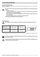
2-INSTALLATION INSTRUCTIONS The requirements in this chapter refer to the regulations of the Italian installation Standard UNI 10683. In any case, always comply with the regulations in force in the country of installation. PELLETS Wood pellets are obtained from compressing sawdust produced during the processing of natural dried wood (without paint). The compactness of the material is guaranteed by the lignin contained in the wood itself and allows pellets to be produced without glue or binders.
2-INSTALLATION INSTRUCTIONS PRECAUTIONS REGARDING INSTALLATION IMPORTANT! Product installation and assembly must be carried out by qualified personnel. The product must be installed in a suitable place for it to be regularly opened and routine maintenance to be performed. The environment must be: • Compliant for proper operation. • Equipped with an adequate smoke expulsion system. • Equipped with ventilation intake from outside. • Equipped with 230V 50 Hz power supply with an EC compliant earth system.
2-INSTALLATION INSTRUCTIONS POSITIONING AND RESTRICTIONS In the case of simultaneous installation with other heating appliances, provide appropriate air inlets for each one (according to the instructions of each product).
2-INSTALLATION INSTRUCTIONS CONNECTION OF THE SMOKE EXHAUST DUCT When drilling the hole for the smoke exhaust pipe, the possible presence of flammable materials must be considered. If the hole must be made through a wooden wall or thermolabile material, the INSTALLER MUST first use the relative wall fitting (minimum diam. 13 cm) and adequately insulate the pipe of the product that passes through it, using suitable insulating material (1.3 - 5 cm thick with minimum thermal conductivity 0.07 W/m°K).
2-INSTALLATION INSTRUCTIONS Always use pipes and fittings with appropriate seals that guarantee tightness. It must be possible to inspect all sections of the flue duct and they must be removable for periodic internal cleaning (T-fitting with inspection hole). Position the product considering all the above requirements and instructions.
2-INSTALLATION INSTRUCTIONS CONNECTION TO THE EXTERNAL AIR INLET It is essential for the room where the product is installed to be adequately ventilated in order to guarantee sufficient air for proper combustion in the appliance. This is possible by means of suitable ventilation openings in the room itself or in an interconnected room through a permanent opening between the rooms.
2-INSTALLATION INSTRUCTIONS CONNECTIONS CONNECTION TO THE CHIMNEY CONNECTION TO AN EXTERNAL DUCT CONNECTION TO THE CHIMNEY WITH AN INSULATED OR DOUBLE-WALL PIPE The internal dimensions of the chimney must not exceed 20x20 cm or 20 cm in diameter. In the case of larger dimensions or bad chimney conditions (e.g. cracks, poor insulation, etc.), it is advisable to fit a stainless steel pipe of suitable diameter throughout the length of the chimney right to the top.
2-INSTALLATION INSTRUCTIONS OPERATING PROBLEMS RELATED TO DRAUGHT DEFECTS IN THE CHIMNEY Among all the weather and geographical conditions that affect chimney operation (rain, fog, snow, altitude a.s.l., exposure to sunlight, orientation to the cardinal points, etc.), the wind is certainly the most determinant.
3-INSTALLATION AND ASSEMBLY DRAWINGS AND CHARACTERISTICS 17.5 274.5 188 199 13 760 523 84.3 237 1026 1070 44 EDERA MULTIAIR DIMENSIONS (in cm) 56.5 66 92.6 277 58.7 764 Technical Dept.
3-INSTALLATION AND ASSEMBLY TECHNICAL CHARACTERISTICS EDERA MULTIAIR Max. overall thermal power: 8 kw / 6880 kcal Min.
3-INSTALLATION AND ASSEMBLY PREPARATION AND UNPACKING The Edera stove is delivered with a number of packages: • The first contains the stove (fig. 1). • The second contains the three painted metal panels (two sides + 1 front). The cardboard with the sides is packed together with the stove package (fig. 2).
3-INSTALLATION AND ASSEMBLY FIGURE 3 - STOVE PACKAGE FASTENING SCREWS 16
3-INSTALLATION AND ASSEMBLY Therefore, the end user is responsible for product storage, disposal or possible recycling in compliance with the relative applicable laws. Position the product without its cladding and connect it to the chimney. Once the connections are complete, assemble the cladding (steel sides). If the product must be connected to an exhaust pipe that goes through the rear wall (to enter the chimney), make sure not to force it in.
3-INSTALLATION AND ASSEMBLY CONNECTION OF THE SMOKE OUTLET PIPE The smoke outlet can be set up on the rear or upper part of the product. If you wish to connect the smoke outlet to the upper part, remove the cap with the two screws from under the top. Then insert the pipe until it engages with the smoke fitting. REMOVE THE CAP FASTENED WITH TWO SCREWS FROM UNDER THE TOP. INSERTING THE PIPE FOR THE UPPER SMOKE OUTLET.
3-INSTALLATION AND ASSEMBLY If you wish to connect the smoke outlet to the rear part, turn the T-fitting towards the rear of the stove. Then connect the pipes. TURN THE T-FITTING FOR THE REAR SMOKE OUTLET. Technical Dept.
3-INSTALLATION AND ASSEMBLY CONNECTING THE HOT AIR DUCTING Once the stove is set in place, the hot air piping can be installed. The air can be channelled by fastening a flexible pipe on the rear part of the stove, in line with the hole on the upper part. Insert the pipe and block it in place with a clamp. The air outlet direction can be changed at any time even if it has been ducted. The stove, by default setting, is designed so that hot air only comes out of the front.
3-INSTALLATION AND ASSEMBLY PLATE SCREW “A” FIG. 5 - KNOB BLOCKING SCREW KNOB FIG. 4 - AIR DIRECTION KNOB Room ventilation can only be set towards the rear wall if there is adequate insulated ducting of the hot air flow. The air outlet pipe can become very hot, approx. 200 °C: therefore, it must be adequately insulated with suitable material, especially points that could come in contact with flammable surfaces or parts that are affected by heat (e.g. change in shades, wiring ducts, plasterboard, etc.).
3-INSTALLATION AND ASSEMBLY A - STOVE B - HOT AIR OUTLET PIPE C - INSULATION WALL D - INSULATION If the wall that is to be drilled through is made of flammable material, the INSTALLER MUST adequately insulate the pipe of the stove that passes through it, using suitable insulating material (1.3 - 5 cm thick with min. thermal conductivity 0.07 W/m°K). However, the pipe inserted in the wall must be adequately insulated in order not to disperse heat and soundproof the released air.
3-INSTALLATION AND ASSEMBLY ASSEMBLING THE SIDE-FRONT AND TOP CLADDING ASSEMBLING THE SIDE AND FRONT PANELS The stove is supplied with the side and front panels packed separately, therefore unpack all the parts before proceeding with the assembly.
3-INSTALLATION AND ASSEMBLY Fit the pins on the lower part of the panel into the pins on the structure of the stove (detail B) in order to assemble the side panel C. Then fasten the panel to the structure of the stove with the two screws supplied.
3-INSTALLATION AND ASSEMBLY ASSEMBLING THE TOP The top does not require particular fastening as it is only placed on the structure of the stove in line with the relative vibration dampers. TOP TOP Technical Dept.
3-INSTALLATION AND ASSEMBLY OPENING/CLOSING THE DOOR ATTENTION! The door must be closed properly for the stove to work correctly. The door of the Edera stove is opened by inserting the cold handle on the opening hook of the door, lifting and pulling. OPENING THE DOOR OF THE EDERA STOVE. ELECTRICAL CONNECTION First connect the power cable to the back of the product and then to a wall socket.
4-OPERATION CONTROL PANEL DISPLAY CONTROL PANEL LOGIC Some useful information is provided below to understand the logic and use of the control panel: • Knob A sets 5 levels of ventilation. The knob turns smoothly from min to max. • Knob B allows the room temperature to be set. The temperature ranges from a min of 15°C to a maximum of 30°C and even in this case, the knob turns smoothly. • Knob C sets 5 flame levels (power); the key turns smoothly. • The product is switched on and off via key D.
4-OPERATION BEFORE START-UP GENERAL PRECAUTIONS Remove all components that could burn from the firebox of the stove and the glass (instructions, various adhesive labels and any polystyrene). Check that the brazier is positioned correctly and rests properly on the base.
4-OPERATION It is good practice to guarantee effective ventilation in the room during the initial start-up, as the stove will emit some smoke and smell of paint. Do not stand close to the stove and air the room. The smoke and smell of paint will disappear after about an hour of operation, however, they are not harmful in any case. The stove will be subject to expansion and contraction during the start-up and cooling phases, therefore light creaking noises may be heard.
4-OPERATION OPERATING MODE The product has the following operating mode. Setting the room temperature (Knob B). The temperature that is desired in the room in which the product is installed is set via control B and ranges from a minimum of 15°C to a maximum of 30°C.
4-OPERATION LOADING THE PELLETS Fuel is loaded from the upper part of the stove by lifting the cover. Slowly pour the pellets into the hopper. Be careful when loading pellets while the stove is hot as the cover could become very hot. No other type of fuel other then pellets, in compliance with above-mentioned specifications, is to be inserted into the hopper. Technical Dept.
4-OPERATION SELECTING THE PELLET LOADING TYPE (Key E) This operation allows the user to set the product in the most appropriate way according to the type of pellets available. Therefore, excessive fuel consumption is avoided, the intended heating capacity is guaranteed and the product integrity is safeguarded.
4-OPERATION CONNECTION TO A ROOM THERMOSTAT The room thermostat is not included with the stove and must be installed by a qualified technician. ATTENTION! The electrical wires must not make contact with the hot parts of the stove. The stove can also be connected to an external thermostat. The procedure below must be followed for the electrical connection: • connect the two wires of the cable coming from the room thermostat to the two free terminals of the connector (position 13 electronic board Chap.
4-OPERATION ROOM THERMOSTAT CABLE POS.13 OPERATION WITH ECO-STOP The Eco-Stop function automatically switches the stove off when the room temperature is met and restarts when it varies. Activation: briefly press the On/Off button 5 times consecutively within 6”. The board emits a long beep as confirmation (3 seconds). • During operation with the Eco-Stop function. The green LED does not remain constantly on but light up for 5 seconds and goes off for 2 seconds.
4-OPERATION CONNECTION TO THE PROGRAMMABLE CHRONOTHERMOSTAT (optional accessory from the manufacturer) The room chrono is not included with the stove and the user is responsible for its installation. Refer to the instructions inside the optional programmable chronothermostat regarding its installation. SAFETY DEVICES The product is supplied with the following safety devices. PRODUCT MAIN SUPPLY SAFETY DEVICE The appliance is protected by a fuse that is located near the switch (I).
4-OPERATION LED 1 ALERT DURING OPERATION LED 1 Off: product is off. LED 1 Green and flashing: starting up. LED 1 Fixed green: product is on at a steady state. LED 1 Orange and flashing: shutdown. LED 1 Red and flashing: alarm in progress. LED 1 Fixed red: product switched off after an alarm. When the product shuts down due to a power cut, LED 1 remains orange and flashing even after having cooled down.
4-OPERATION LED INDICATION TYPE OF PROBLEM SOLUTION Led - 2 The fire failed to ignite Check the level of pellets in the hopper. Check that the brazier rests correctly in its seat and has no visible deposits of unburned pellets. Led - 1 The fire goes off abnormally Check the level of pellets in the hopper. Check that the brazier rests correctly in its seat and has no visible deposits of unburned pellets. Led 0 The pellet hopper temperature exceeds the intended safety threshold.
5-MAINTENANCE AND CLEANING EXAMPLE OF A CLEAN BRAZIER EXAMPLE OF A DIRTY BRAZIER ATTENTION! All the cleaning operations of all parts must be performed with a completely cold product and the plug disconnected. The product requires little maintenance if used with certified good quality pellets. DAILY OR WEEKLY CLEANING PERFORMED BY THE USER BEFORE EACH START-UP Clean the ash and any deposits in the brazier that could clog the air passage holes.
5-MAINTENANCE AND CLEANING CLEANING THE GLASS It is recommended to clean the ceramic glass with a dry brush, or if it is very dirty, spray a little specific detergent and clean with a cloth. ATTENTION! Do not use abrasive products and do not spray the glass spray cleaner on the painted parts or the door gaskets (ceramic fibre cord).
5-MAINTENANCE AND CLEANING CLEANING THE UPPER EXCHANGER CLEANING THE EDERA STOVE T-FITTING CLEANING THE SMOKE DUCT AND GENERAL CHECKS Clean the smoke exhaust, especially around the T-fittings, curves and any horizontal sections. Remove the side to clean the T-fitting. For information on cleaning the flue, contact a chimney sweeper. Check the tightness of the ceramic fibre gaskets on the door of the stove.
5-MAINTENANCE AND CLEANING END-OF-SEASON SHUTDOWN At the end of each season, before switching the product off, it is recommended to remove all the pellets from the hopper with a vacuum cleaner that has a long pipe. The appliance must be disconnected from the mains when it is not used. It is recommended to remove the power cable for additional safety, especially in the presence of children.
6-PROBLEMS/CAUSES/SOLUTIONS ATTENTION: All repairs must only be carried out by a specialised technician, with the product switched off and the plug disconnected. If the product is NOT used as described in this instruction manual, the manufacturer declines all liability for any damage caused to persons and property. All the necessary measures and/or precautions must be adopted when performing maintenance, cleaning and repairs. • Do not tamper with the safety devices. • Do not remove the safety devices.
6-PROBLEMS/CAUSES/SOLUTIONS ANOMALY LED POSSIBLE CAUSES SOLUTIONS The product indicates that the pellet hopper temperature exceeds the safety threshold. Led 0 Pellet load is excessive. Wait for the product to cool down, restart it and decrease the pellet load. Wait for the product to cool down, restart it and increase the fan power via knob A. Room fan power is too low. The door is not closed properly or the gaskets are worn. The combustion chamber is dirty.
6-PROBLEMS/CAUSES/SOLUTIONS ANOMALY POSSIBLE CAUSES Pellets accumulate in the Pellet load is excessive. brazier. Insufficient combustion air. Damp or unsuitable pellets. SOLUTIONS Decrease the pellet load. Make sure the combustion air inlet in the rear part of the product is not clogged or obstructed. The door is open. Empty the hopper from the unsuitable pellets and replace them with those recommended by the manufacturer. Make sure the door is closed. Clogged smoke outlet. Clean the smoke exhaust.
7-WIRING DIAGRAMS MOTHERBOARD WIRING KEY 1. 2. 3. 4. 5. 6. 7. 8. CONTROL PANEL ROOM PROBE RED + BLUE - SMOKE PROBE FUSE SWITCH SPARK PLUG SMOKE EXPULSION FANI GEAR MOTOR 9. 10. 11. 12. 13. 14. CONTACT THERMOSTAT AIR FAN WHITE/RED/BLACK OR BLUE SMOKE EXPULSION FAN REV CONTROL CHRONOTHERMOSTAT ROOM THERMOSTAT PRESSURE SWITCH N.B. The wiring of the individual components is fitted with pre-wired connectors of different sizes. Technical Dept.
Via La Croce n°8 33074 Vigonovo di Fontanafredda (PN) – ITALY Telefono: 0434/599599 r.a. Fax: 0434/599598 Internet: www.mcz.it e-mail: info.red@mcz.it For further technical information regarding installation or operation please contact the TECHNICAL ASSISTANCE – AFTER-SALES DEPARTMENT Monday to Friday 8.00 to 12.00 and 14.00 to 18.00 8901219300 REV.