
Installation manual

45
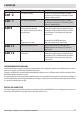
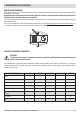
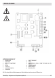
7-WIRING DIAGRAMS
MOTHERBOARD WIRING KEY
1. CONTROL PANEL
2. ROOM PROBE
3. RED + BLUE - SMOKE PROBE
4. FUSE
5. SWITCH
6. SPARK PLUG
7. SMOKE EXPULSION FANI
8. GEAR MOTOR
9. CONTACT THERMOSTAT
10. AIR FAN
11. WHITE/RED/BLACK OR BLUE SMOKE EXPULSION FAN REV
CONTROL
12. CHRONOTHERMOSTAT
13. ROOM THERMOSTAT
14. PRESSURE SWITCH
N.B. The wiring of the individual components is tted with pre-wired connectors of dierent sizes.
Technical Dept. - All rights reserved - Reproduction is prohibited