
Operation Manual

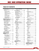


Build 31 v31.6.16 Beta
JUNE 22, 2011 © 2007-2011 RED.COM INC.
9
IMAGE PROCESSING
The digital images received from the MYSTERIUM or MYSTERIUM X sensors are formatted as pixel de-
fect corrected (but not color processed) RAW data - similar to digital RAW stills cameras.
The sequence of RAW images received from the sensor is compressed using proprietary 12-bit RED-
CODE™ RAW compression. The REDCODE RAW data recorded is independent of the RGB signal moni-
tored in the monitoring path. ISO, White Balance and other RGB color adjustments made to the RGB
monitoring path are not burned into the recorded 12-bit REDCODE RAW data.
REDCODE RAW images can be stored on Compact Flash, RED-DRIVE®, RED-RAM® or RED-RAID®
media.
The camera’s RGB monitoring path independently converts the sequence of RAW images received from
the sensor to white balanced 10-bit 1280 x 720 pixel RGB 4:4:4 video. This signal may be modified using
ISO, White Balance and other RGB color adjustments and provides monitor feeds for the RED EVF,
BOMB (Pro) EVF, RED LCD, Preview HD-SDI and HDMI outputs.
If a specific set of RGB image processing values are desired to be repeatable on-set, a LOOK file may be
created either by the camera or the REDCINE-X™ application software.
AUDIO RECORDING
The RED ONE includes four channels of analog audio input processing, Peak Level meter, headphone
monitor and 2-channel balanced analog audio output. Audio is digitized at 24-bit depth and 48 KHz and
recorded in synchronization with video and timecode to the attached media. Digital audio is also embed-
ded in the HDMI, Preview and Program HD-SDI outputs.
Line Level and Microphone Level analog audio input signals are routed via a high quality A/D and pre-
amplifier, whose gain stage may be controlled using the Input Level control to achieve the desired audio
reference / recording level.
To assist with audio operating reference level setup, the camera provides a color-coded 3dB per division
Peak Level meter with 0dBu (-20dBFS) Witness Mark in the Graphical User Interface.
Peak Level meter range is –34dBu to +20dBu (-54dBFS to 0dBFS) and provides clip indication.
LINE LEVEL INPUTS
Line level audio inputs are designed to operate at unity gain (0dB Input Level); therefore an appropriate
line output level should be established by your field production mixer or other external signal source.
Reference signal level for Line inputs is 0dBu / 0.775 volts RMS / -20dBFS when operating at 0dB Input
Level. The maximum input signal that can be applied before the onset of input signal clipping is +18dBu /
6.5 volts RMS / - 2dBFS. I.e. this setting supports a guaranteed minimum of 18dB of input signal head-
room above reference, plus the maximum available Signal to Noise Ratio for the resulting 24-bit digital
recording.
MICROPHONE LEVEL INPUTS
The recorded signal levels of Microphone inputs are affected by the sensitivity of the microphone and the
Input Level setting. Range is +36dB to +54dB, with a default value of +36dB. The camera operator
should choose an Input Level that aligns the input signal to the reference line drawn vertically through the
camera’s PPM, indicating 0dBu.