
Operation Manual


Build 31 v31.6.16 Beta
© 2007-2011 RED.COM INC. JUNE 22, 2011
130 130
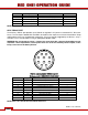
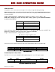
Pin: Signal Description Direction
1
Ground Camera ground -
2
TIMECODE_IN_P Serial timecode input, positive In
3
TIMECODE_IN_N Serial timecode input, negative In
4
- - No connect - -
5
TIMECODE_OUT Serial timecode output Out
NOTE: Pin 4 is a not used. Do not tie-in to ground.
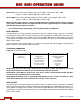
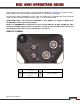
AUX / RS232 PORT
The Auxiliary / RS232 port provides up to 500mA of regulated +12V power to motorized 2/3” B4 mount
lenses. The two inputs labeled SW1 and SW2 are fixed function inputs that activate Record Start / Stop
and Playback of the last recorded clip respectively. These are typically triggered by the B4 lens, or by a
controller such as Preston MDR-2 using an appropriate adaptor cable.
WARNING: Do not attempt to power a cinema lens motor from this connector. Depending on your
maximum current requirement, extract power from one of the two Auxiliary Power outputs, or the
D-Tap connector on the battery V-Plate.
5
10
8
2
9
7
6
4
3
1
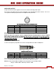
View into camera Auxiliary / RS232 connector
Mating connector: LEMO FHG.1B.310.CLAD62Z
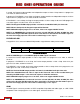
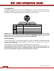
Pin: Signal Description Direction
1
GND Camera ground --
2
RTX RS232 Transmit Data Out
3
+12V Regulated 12V output, 500mA max. Out
4
- -- Reserved: do not connect -- --
5
SW1 “W Reserved: do not connect In
6
- -- Reserved: do not connect -- --
7
SW2 “W Reserved: do not connect -- In
8
RRX RS232 Receive Data In
9
- -- Reserved: do not connect -- --
10
- -- Reserved: do not connect -- --
NOTE: Pins 4, 6, 9 and 10 are reserved for future use.