RED DSMC OPERATION GUIDE: WEAPON W E A P O N ( C a r b on F i b e r ) | W E A P O N ( M a g ne s i u m ) V6.1| RED DRAGON RED.
R E D D S M C O P E R AT I O N G U I D E : W E A P O N TABLE OF CONTENTS Disclaimer 3 Copyright Notice 3 Trademark Disclaimer 3 Compliance Statements 4 Safety Instructions 6 Battery Storage and Handling 7 Shipping Disclaimer 7 Chapter 1: WEAPON Introduction 8 Read Before You Shoot 8 DSMC BRAIN 9 RED Digital Sensors 9 R3D File Format and REDCODE 10 Shoot For Video and Stills 11 Post Production with REDCINE-X PRO 11 HDRx and MAGIC MOTION 12 Additional Resources 12 Chapter 2: WEAPON System Compo
R E D D S M C O P E R AT I O N G U I D E : W E A P O N DISCLAIMER RED has made every effort to provide clear and accurate information in these installation instructions, which are provided solely for the user’s information. While thought to be accurate, the information in this document is provided strictly “as is” and RED will not be held responsible for issues arising from typographical errors or user’s interpretation of the language used herein that is different from that intended by RED.
R E D D S M C O P E R AT I O N G U I D E : W E A P O N COMPLIANCE STATEMENTS CAUTION: Regulations of the FCC and FAA prohibit airborne operation of radio-frequency wireless devices because there signals could interfere with critical aircraft instruments. INDUSTRIAL CANADA EMISSION COMPLIANCE STATEMENTS This device complies with Industry Canada license-exempt RSS standards RSS 139 and RSS 210.
R E D D S M C O P E R AT I O N G U I D E : W E A P O N INFORMATION NORWAY Products with the CE marking comply with the EMC Directive (2004/108/EC) and the Low Voltage Directive (2006/95/EC) issued by the Commission of the European Community. Compliance with these directives implies conformity to the following European Product Family Standards.
R E D D S M C O P E R AT I O N G U I D E : W E A P O N SAFETY INSTRUCTIONS DO NOT use the camera or accessories near water. Avoid exposing your camera to moisture. The unit is not waterproof, so contact with water could cause permanent damage to the unit as well as electric shock and serious injury to the user.
R E D D S M C O P E R AT I O N G U I D E : W E A P O N BATTERY STORAGE AND HANDLING WARNING: Failure to read, understand, and follow these instructions may result in overheating, chemical leakage, smoke emission, fire, or other potentially harmful results. Always follow proper battery handling and storage practices. Improper handling and/or failure to abide by proper storage instructions may cause permanent damage to batteries, or degrade battery charge holding capacity.
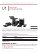
R E D D S M C O P E R AT I O N G U I D E : W E A P O N 01 WEAPON INTRODUCTION WEAPON System The WEAPON ® cameras are part of the RED ® Digital Still and Motion Camera (DSMC ® ) system. The DSMC family includes WEAPON, EPIC, and SCARLET ® cameras. With an ultra-high megapixel count, high frame rate, significant processing power, high dynamic range, and the advantages of a raw file format, each DSMC offers the ability to simultaneously capture video and stills. This guide is for WEAPON only.
R E D D S M C O P E R AT I O N G U I D E : W E A P O N DSMC BRAIN WEAPON (Carbon Fiber) At the center of the RED modular system is the DSMC BRAIN ® , housing the critical image capture electronics and digital image sensor. The expansive RED arsenal of DSMC modules, monitors, lens mounts, controllers, power, media, and other accessories supports WEAPON BRAINs. Modular DSMC lens mounts enable you to use your existing Canon ® , Nikon ® , Leica-M ® , and PL lenses to capture the perfect shot.
R E D D S M C O P E R AT I O N G U I D E : W E A P O N RED DRAGON SENSOR (6K) RED DRAGON 6K Resolution The RED DRAGON (6K) sensor captures over nine (9) times more resolution than standard HD. The result is unrivaled detail and impressive native exposure that exceeds 35mm film in both latitude and image density. The RED DRAGON (6K) sensor is a model for image innovation, leading the way in the evolution of digital cinema technology.
R E D D S M C O P E R AT I O N G U I D E : W E A P O N RAW data is recorded independently of any RGB domain color processing such as ISO, White Balance, or other RGB color space settings. Instead, color parameters are saved as reference metadata; that is, color is not burned into the recorded RAW data.
R E D D S M C O P E R AT I O N G U I D E : W E A P O N HDRX AND MAGIC MOTION HDRx HDRX HDRx extends dynamic range up to six (6) stops by simultaneously capturing two (2) images of identical resolution and frame rate. The first image is a normally exposed track (A-track), while the second is an underexposed track (X-track) with an exposure value that reflects the additional stops of highlight protection.
R E D D S M C O P E R AT I O N G U I D E : W E A P O N 02 WEAPON SYSTEM COMPONENTS WEAPON (Woven CF) Package This section provides an overview of the WEAPON ® system components, including: “BRAIN” on page 14 “RED MINI-MAG System” on page 19 “WEAPON Expanders” on page 20 “RED Batteries and Chargers” on page 23 “Displays and Electronic Viewfinders” on page 24 “LEMO Adaptors” on page 28 “Camera Control Modules” on page 29 “Lens Mounts” on page 31 “Interchangeable OLPFs” o
R E D D S M C O P E R AT I O N G U I D E : W E A P O N BRAIN WEAPON (Carbon Fiber) The DSMC ® BRAIN ® is the image processing center of the DSMC system and supports power, media, and other modules. The only ports on the WEAPON BRAIN are the WEAPON Top Handle port and EVF/LCD ports. A port expander or power module is required to power the camera. All other input/ouput (I/O) ports are available only via expanders and other modules.
R E D D S M C O P E R AT I O N G U I D E : W E A P O N BRAIN LEDS This section describes the LED functions for the WEAPON BRAIN.
R E D D S M C O P E R AT I O N G U I D E : W E A P O N BRAIN CONNECTORS, FOCUS HOOK, AND BACK FOCUS 2 1 3 4 5 6 WEAPON BRAIN Ports and Features This section describes the ports and features on the BRAIN. NOTE: For more information on how to install the focus hook, go to “Install the Focus Hook” on page 36. # PORT/ITEM DESCRIPTION 1 Primary EVF/LCD Port 1 Mount the WEAPON RED Touch 7.
R E D D S M C O P E R AT I O N G U I D E : W E A P O N WEAPON MEDIA BAY CONTROLS 1 2 3 WEAPON Media Bay Controls This section describes the control functions for the media bay. # CONTROL DESCRIPTION 1 User Key 1 Programmable key User Key 1 + 2 Press: Eject Media 2 REC button Programmable key Full Press: Record Toggle Half Press: AF Start 3 User Key 2 Programmable key User Key 1 + 2 Press: Eject Media For more information, see the DSMC Media Operation Guide, available at www.red.com/downloads.
R E D D S M C O P E R AT I O N G U I D E : W E A P O N WEAPON MEDIA BAY LEDS 1 2 WEAPON Media Bay LEDs This section describes the LED functions for the media bay.
R E D D S M C O P E R AT I O N G U I D E : W E A P O N RED MINI-MAG SYSTEM RED MINI-MAG (1TB) RED MINI-MAG ® SSDs deliver fast and reliable recording options for your camera. A RED STATION ® enables you to connect media to your computer for offloading and editing.
R E D D S M C O P E R AT I O N G U I D E : W E A P O N WEAPON EXPANDERS NOTE: Only one (1) expander module can be used at a time. RED offers the following WEAPON expanders: ITEM PART NUMBER WEAPON Base Expander 720-0033 WEAPON REDVOLT Expander 720-0040 WEAPON Jetpack Expander 720-0039 WEAPON BASE EXPANDER WEAPON Base Expander The WEAPON Base Expander is an ideal connector module for general input/output (I/O) needs.
R E D D S M C O P E R AT I O N G U I D E : W E A P O N WEAPON REDVOLT EXPANDER WEAPON REDVOLT Expander Designed for advanced configurations, the WEAPON REDVOLT ® Expander mounts directly to the BRAIN and offers an expansive array of I/O connectors and functionality available for the WEAPON system. The WEAPON REDVOLT Expander features ports for power in (DC IN), Genlock (BNC), Timecode (LEMO), GIG-E, and more.
R E D D S M C O P E R AT I O N G U I D E : W E A P O N WEAPON JETPACK EXPANDER WEAPON Jetpack Expander The WEAPON Jetpack Expander is specifically designed for aerial, gimbal, handheld, and other lightweight/ remote configurations. This expander features standard connectors for power (DC-IN), CTRL, and SYNC for all of your Timecode and Genlock needs.
R E D D S M C O P E R AT I O N G U I D E : W E A P O N POWER MODULES RED offers the following WEAPON power modules: ITEM PART NUMBER WEAPON REDVOLT XL Module 740-0034 WEAPON REDVOLT XL MODULE WEAPON REDVOLT XL Module The WEAPON REDVOLT XL Module mounts seamlessly to the back of the BRAIN—and select other I/O expanders—to provide support for long-lasting and rechargeable REDVOLT XL batteries.
R E D D S M C O P E R AT I O N G U I D E : W E A P O N DISPLAYS AND ELECTRONIC VIEWFINDERS RED offers the following displays and electronic viewfinders (EVFs): ITEM RESOLUTION PART NUMBER 1920 x 1136 730-0018 WEAPON RED Touch 4.7" LCD 1 1280 x 720 730-0019 RED Touch 5.0" LCD 2 800 x 400 730-0008 RED Touch 7.0" LCD 1920 x 1136 730-0007 RED Touch 9.
R E D D S M C O P E R AT I O N G U I D E : W E A P O N RED LCDS WEAPON RED Touch 7.0" LCD RED displays provide important camera parameters on the graphical user interface (GUI) and offer a variety of monitor viewing options. RED touchscreen displays enable you to use gestures to navigate menus and adjust camera parameters. RED displays feature 8-bit RGB, 4:4:4 progressive scan, providing up to 16.7 million colors and up to 70% NTSC color gamut.
R E D D S M C O P E R AT I O N G U I D E : W E A P O N BOMB EVFS The BOMB EVF (LCOS) and BOMB EVF (OLED) deliver specialized viewing solutions for the DSMC. The BOMB EVF (LCOS) is a high-definition, lightweight, and low-profile viewfinder. The BOMB EVF (OLED) uses OLED technology, providing deeper blacks and more color accurate images. ITEM BOMB EVF (LCOS) 1 BOMB EVF (OLED) 1 CONTRAST RATIO DIOPTER RANGE 1000:1 typical 2.0 to –5.0.1 >10,000:1 typical 2.0 to –5.0.1 1.
R E D D S M C O P E R AT I O N G U I D E : W E A P O N WEAPON RED EVF The WEAPON RED EVF (OLED) is a high definition electronic viewfinder designed as the ideal single-viewer monitoring solution. Featuring the latest OLED technology, this EVF provides an unmatched personal viewing experience with a 1080p OLED micro-display, and improved color accuracy with 30-bit RGB color represenation. View and monitor your RED footage as it is intended with truer colors and deeper blacks in a larger field of view.
R E D D S M C O P E R AT I O N G U I D E : W E A P O N LEMO ADAPTORS This section describes the WEAPON LEMO Adaptor A and the WEAPON LEMO Adaptor B. These adaptors enable you to use EPIC/SCARLET displays with your WEAPON camera and use WEAPON displays with your EPIC/SCARLET camera. For more information on available displays, go to “Displays and Electronic Viewfinders” on page 24.
R E D D S M C O P E R AT I O N G U I D E : W E A P O N CAMERA CONTROL MODULES This section describes the camera control modules. These devices provide a wide array of programmable buttons, controls, and other features to interact with the camera. RED offers the following remotes and controls: ITEM PART NUMBER 1 720-0041 WEAPON Sidekick (Woven CF) 1 720-0036 WEAPON Sidekick (Magnesium) 1 720-0032 WEAPON Top Handle 720-0035 WEAPON Sidekick (Forged CF) 1.
R E D D S M C O P E R AT I O N G U I D E : W E A P O N WEAPON SIDEKICK WEAPON Sidekick (Woven CF) The WEAPON Sidekick is a lightweight interface solution that offers intuitive integrated control over critical camera parameters. Engineered exclusively for WEAPON, this low profile interface provides full access to basic and advanced menus via a 1.7" OLED display. The rotary dial, D-Pad, function buttons, and configurable preset buttons provide an improved method of controlling your camera.
R E D D S M C O P E R AT I O N G U I D E : W E A P O N LENS MOUNTS DSMC Mg PL Mount 2.0 RED offers the following DSMC lens mounts: ITEM PART NUMBER DSMC Mg PL Mount 2.
R E D D S M C O P E R AT I O N G U I D E : W E A P O N 03 WEAPON BASIC OPERATIONS POWER OPERATIONS This section describes the basic power operations of the WEAPON ® system. For more information, see the DSMC Power Operation Guide, available at www.red.com/downloads. WARNING: Modules, displays, and accessories are NOT HOT SWAPPABLE, meaning that you cannot remove or install the item while the camera is turned on. Before installing or removing a module, display, or accessory, you MUST turn off the camera.
R E D D S M C O P E R AT I O N G U I D E : W E A P O N TURN ON THE BRAIN 1. Attach a power source to the BRAIN. The Power Status LED illuminates red, indicating that an appropriate power source is connected. 2. Press and release the PWR/REC button on the right side of the BRAIN. The Power Status LED turns off, and within five (5) seconds illuminates yellow as the BRAIN turns on. The Power Status LED then illuminates green to confirm that the BRAIN is turned on and ready to use.
R E D D S M C O P E R AT I O N G U I D E : W E A P O N REMOVE THE WEAPON SIDEKICK This section applies to the following items: WEAPON Sidekick (Forged CF) WEAPON Sidekick (Woven CF) WEAPON Sidekick (Magnesium) NOTE: Each WEAPON Sidekick is compatible with both WEAPON (Carbon Fiber) and WEAPON (Magnesium). WARNING: Before installing or removing the WEAPON Sidekick, you MUST turn off the BRAIN. REQUIRED TOOL: T10 TORX driver 1. Turn off the BRAIN. 2.
R E D D S M C O P E R AT I O N G U I D E : W E A P O N INSTALL THE WEAPON REDVOLT XL MODULE The WEAPON REDVOLT XL Module mounts to the rear of the following items: WEAPON BRAIN WEAPON Base Expander WEAPON REDVOLT Expander WARNING: Before installing or removing the WEAPON REDVOLT XL Module, you MUST turn off the BRAIN. REQUIRED TOOL: T20 TORX driver 1. Turn off the BRAIN. 2.
R E D D S M C O P E R AT I O N G U I D E : W E A P O N REMOVE THE MEDIA BAY To troubleshoot issues with the media bay or SSD, you may need to remove and re-install the media bay. Unless you are troubleshooting media-related issues, DO NOT remove the media bay. WARNING: Before installing or removing the media bay, you MUST turn off the BRAIN. REQUIRED TOOL: T10 TORX driver 1. Turn off the BRAIN. 2. Loosen the four (4) captive screws in a cross pattern (“X” pattern) using a T10 TORX driver. 3.
R E D D S M C O P E R AT I O N G U I D E : W E A P O N INTERCHANGEABLE OLPF SYSTEM This section describes the process for swapping an interchangeable OLPF. WARNING: Read these instructions carefully and in their entirety before removing or installing an interchangeable OLPF. Damage caused to the OLPF module, camera, or sensor due to improper handling or use is not covered under warranty. WARNING: Once an interchangeable OLPF is removed from the BRAIN, the sensor is exposed.
R E D D S M C O P E R AT I O N G U I D E : W E A P O N USE A TRIPOD OR MONOPOD This section describes the WEAPON mounting points and mounting equipment for use with a tripod or monopod. The WEAPON is equipped with two (2) 3/8-16 mounting holes and one (1) 1/4-20 mounting hole on the bottom of the BRAIN. These mounting points are designed for use with a variety of mounting plates and hardware, to support tripods and other support systems.
R E D D S M C O P E R AT I O N G U I D E : W E A P O N VIDEO MONITOR CATEGORIES NOTE: HD-SDI and HDMI ports are only available on select WEAPON expanders. For more information, go to “Input/Output Connectors” on page 161. Video monitor outputs are separated into three (3) categories: VIEWFINDER: The Upper Status Row, Live Action Area, and Lower Status Row display. Default output is the EVF/LCD connector located on top of the camera.
R E D D S M C O P E R AT I O N G U I D E : W E A P O N EXTERNAL RECORD NOTE: HD-SDI and HDMI ports are only available on select WEAPON expanders. For more information, go to “Input/Output Connectors” on page 161. You can record to an external recorder without recording to an SSD. To record to an external device only, follow the instructions below: 1. Attach a WEAPON expander that has an HD-SDI or HDMI port. 2. Connect the camera to an external recorder with an HD-SDI or HDMI cable. 3.
R E D D S M C O P E R AT I O N G U I D E : W E A P O N 04 BASIC MENUS AND CONTROLS This chapter describes the WEAPON ® Basic Menu, controls, including: “Upper Status Row (Basic Menu)” on page 42 “Live Action Area” on page 46 “Lower Status Row” on page 47 “Navigation Controls” on page 52 WEAPON GUI MENU INTRODUCTION 1 2 3 GUI Control Menu This section describes the structure and layout of the WEAPON graphical user interface (GUI) that overlays the video monitor signal.
R E D D S M C O P E R AT I O N G U I D E : W E A P O N UPPER STATUS ROW (BASIC MENU) The Upper Status Row displays basic project parameters. The currently selected parameter in the Upper Status Row is underlined with a red bar. The Upper Status Row is also known as the Basic Menu. 9 1 2 3 4 5 6 7 8 Upper Status Row The Upper Status Row includes the following GUI elements: # ITEM DESCRIPTION FOR MORE INFORMATION, GO TO...
R E D D S M C O P E R AT I O N G U I D E : W E A P O N ACCESS ADVANCED MENUS For every Upper Status Row item, you can select the Advanced... button to access the related menu in the Advanced Menus. For example, select Advanced... in the Frame Rate menu to open Menu > Settings > Project > Frame Rate. For more information about Advanced Menus, go to “Advanced Menus” on page 57. Select “Advanced...” Button “Advanced...” Menu COPYRIGHT © 2015 RED.COM, INC 955-0116_V6.
R E D D S M C O P E R AT I O N G U I D E : W E A P O N FEATURE: EDIT LIST Select the Edit List... button in the Upper Status Row menus to change the values that display for each setting. For example, if you open the Frame Rate menu and select Edit List..., the camera lets you add or remove values to available frame rates. Select “Edit List...” Button “Edit List...” Menu COPYRIGHT © 2015 RED.COM, INC 955-0116_V6.
R E D D S M C O P E R AT I O N G U I D E : W E A P O N APERTURE The aperture (also known as the T stop or F stop) parameter displays when a compatible mount and lens are installed. The aperture controls the depth of field of the image and, in combination with the shutter speed/angle setting, controls the amount of light that reaches the sensor (exposure). Increasing the aperture to a higher number increases the depth of field, but reduces the exposure (brightness).
R E D D S M C O P E R AT I O N G U I D E : W E A P O N LIVE ACTION AREA The Live Action Area contains the recorded image area plus Surround View look around area, plus overlays for Frame Guides, Safe Action/Safe Title, Clip Name, and Timecode values. The color of each overlay can be customized to maximize the contrast between the guide(s) and scene being captured. 2 1 4 3 5 6 Live Action Area The Live Action Area includes the following GUI elements: # ITEM DESCRIPTION FOR MORE INFORMATION, GO TO..
R E D D S M C O P E R AT I O N G U I D E : W E A P O N LOWER STATUS ROW The Lower Status Row provides access to key system information and camera values. 1 2 3 4 5 6 Lower Status Row: Motion The Lower Status Row in Motion mode provides key system information and camera values, including: # ITEM SUB-ITEM/DESCRIPTION FOR MORE INFORMATION, GO TO...
R E D D S M C O P E R AT I O N G U I D E : W E A P O N CAMERA MODE The Camera Mode allows you to seamlessly toggle between Motion mode, Stills mode, and Playback. To select a camera mode, select the Camera Mode icon in the Lower Status Bar, swipe up, and select a camera mode. NOTE: Setting adjustments made in Stills mode do not affect the settings in Motion mode, and vice versa.
R E D D S M C O P E R AT I O N G U I D E : W E A P O N HISTOGRAM This section describes the elements that comprise the Histogram section in the Lower Status Row. This section of the GUI helps ensure that recorded footage is properly exposed. Tap the Histogram in the Lower Status Row to access the Tools menu. For more information, go to “Tools” on page 58. 1 2 4 3 Histogram (Exposure) # ITEM DESCRIPTION 1 RAW Level Bar (left) 1 Also known as a “goal post”.
R E D D S M C O P E R AT I O N G U I D E : W E A P O N TC INDICATOR The TC indicator shows the current timecode status. Gray: No analog timecode is detected. Red: Analog timecode is detected but not enabled. Green: Analog timecode is used to jam the time of day timecode. For more information, go to “Timecode, Genlock, Multi-Camera Setup” on page 132. GEN INDICATOR The GEN indicator shows the current genlock status.
R E D D S M C O P E R AT I O N G U I D E : W E A P O N POWER STATUS The Power Status element displays the current supply voltage or remaining battery capacity. Tap the Power Status element to access the Power menu. For more information, go to “Power Menu” on page 114. DC IN SUPPLY VOLTAGE When powering the DSMC via DC power, the current voltage displays. When powering the DSMC using batteries, the remaining battery capacity displays.
R E D D S M C O P E R AT I O N G U I D E : W E A P O N NAVIGATION CONTROLS This section describes basic controls for navigating the DSMC menus. TOUCHSCREEN NAVIGATION RED Touch displays offer intuitive menu control and four (4) programmable buttons. 1 2 3 4 RED Touch 7.
R E D D S M C O P E R AT I O N G U I D E : W E A P O N SWIPE-UP MENU The Swipe-Up Menu is available in the Lower Status Row on RED Touch displays and provides Swipe-Up Shortcuts for Motion mode, Stills mode, and Playback. For example, select the Camera Mode icon in the Lower Status Bar, swipe up, and select a Camera Mode.
R E D D S M C O P E R AT I O N G U I D E : W E A P O N NAVIGATION GROUP The Navigation Group is the primary control interface on the WEAPON Sidekick.
R E D D S M C O P E R AT I O N G U I D E : W E A P O N WEAPON SIDEKICK This section describes the controls and display of the WEAPON Sidekick.
R E D D S M C O P E R AT I O N G U I D E : W E A P O N WEAPON SIDEKICK DISPLAY The WEAPON Sidekick OLED display provides basic camera parameters during operation.
R E D D S M C O P E R AT I O N G U I D E : W E A P O N 05 ADVANCED MENUS ADVANCED MENUS DSMC Advanced Menu The Advanced Menus include: ADVANCED MENU DESCRIPTION FOR MORE INFORMATION, GO TO...
R E D D S M C O P E R AT I O N G U I D E : W E A P O N SETTINGS MENU Settings Menu The Settings menu includes: Display, Look, Project, Audio, Recording, Setup, and Maintenance. DISPLAY The Display menu includes: Tools, Zebra, Monitor Control, Modes, Guides, and Test Signal. TOOLS The Tools menu provides access to false color and display modes. For more information, see the Exposure with RED Cameras: False Color & Zebra Tools article, available at www. red.
R E D D S M C O P E R AT I O N G U I D E : W E A P O N VIDEO Displays a color overlay that indicates the video level of the RGB monitor path (calibrated to the SMPTE test signal). When enabled, the “V√” indicator displays in the Lower Status Row. Colors are based on the RGB levels of the video out signal (that is, the “cooked” look, and not RAW data). The RGB settings (settings in the Look menu) affect the Video indicators.
R E D D S M C O P E R AT I O N G U I D E : W E A P O N DISPLAY MODES Display mode options include: Magnify, RAW, and Horizon. MAGNIFY Displays the central region of the sensor in 1:1 pixel resolution. When enabled, the 1:1 text in the Lower Status Row turns green, and the AF Window and the magnified region display. The AF Window determines the center point of the magnified region. If the lens or lens mount is not capable of autofocus with the DSMC, use Confirm mode to turn on the AF Window.
R E D D S M C O P E R AT I O N G U I D E : W E A P O N ZEBRA Use Zebra mode to enable and adjust the upper and lower values for two (2) independent zebra indicators. Use Zebra 1 for highlight exposure, and use Zebra 2 for mid-tones or shadows. Zebras are visible in Magnify mode and are disabled by default. As with other IRE-based modes, zebra mode is applicable to the current ISO and Look settings, and not the RAW image.
R E D D S M C O P E R AT I O N G U I D E : W E A P O N FREQUENCY Determines the monitor frequency. Available frequencies depend on the selected monitor. The LCD resolution defaults to 60.00 Hz, which is the optimal refresh rate for the RED LCDs. For HD-SDI monitors, the frequency depends on the project time base. For more information, go to “3G-SDI (HD-SDI) Out” on page 165 and “HDMI Out” on page 166. TOOLS Enables the false color modes on the monitor. For more information, go to “Tools” on page 58.
R E D D S M C O P E R AT I O N G U I D E : W E A P O N OVERLAYS Create custom overlays that include specific items. Overlays can be stored on the camera or transferred to SSD to be shared with other cameras. Camera: Overlays saved internally on the camera display in the Overlay drop-down menu on the Monitor Control > Monitor tab. Media: Overlays saved to an SSD can be found at On Media: \overlays:.
R E D D S M C O P E R AT I O N G U I D E : W E A P O N 5. Select a button on the matrix to add a user interface element to that position on the matrix. By default, the Magnify indicator (MI) is on the top left, the Record indicator (REC) is on the top right, the Clip Name (CLIP) is on the bottom left, and the Timecode (TC) is on the bottom right. Selecting one (1) of the buttons opens a new dialog that lets you choose a user interface element. 6. Select the Item that you want to add. 7.
R E D D S M C O P E R AT I O N G U I D E : W E A P O N BRIGHTNESS Control the brightness of each LCD and EVF. Move to the right for a brighter display; move to the left for a dimmer display. ADVANCED Provides access to additional monitor settings. GESTURES Pinch to Magnify: Move two (2) fingers apart or together to toggle 1:1 Magnify. For more information, go to “Magnify” on page 60. Double-Tap Right 25% to Record: Double-tap the right 25% of the video area on the LCD to toggle record.
R E D D S M C O P E R AT I O N G U I D E : W E A P O N MODES Use the Modes menu to determine how the following settings display: Camera Lens CAMERA TAB Display Mode: Camera EXPOSURE Time (Absolute): Displays the exposure time in seconds (1/xx sec). When you change the frame rate in this mode, the shutter time stays the same, but the shutter angle changes. Time (Absolute) is the default. Angle (Relative): Displays the exposure as an angle (1–360°).
R E D D S M C O P E R AT I O N G U I D E : W E A P O N LENS TAB Display Mode: Lens APERTURE 1/4 F#: Aperture increments in 1/4 stops. 1/3 F#: Aperture increments in 1/3 stops. (Default) FOCUS DISTANCE Metric: Displays lens focus distances in meters. Imperial: Displays lens focus distances in feet and inches. (Default) MOTION MOUNT ND AND MOTION MOUNT ISO PULL Only applicable when using a DSMC RED MOTION MOUNT ® .
R E D D S M C O P E R AT I O N G U I D E : W E A P O N WIDTH/HEIGHT The Width/Height fields replace the Scale field when you select Absolute from the Mode drop-down menu. Select the values for the width and height of the guide in pixels. OFFSET X/Y Percentage to offset guide from its default centered position. Available range is 0–100%. 100%: Right-aligned (for X offset) and bottom-aligned (for Y offset). -100%: Left-aligned (for X offset) and top-aligned (for Y offset).
R E D D S M C O P E R AT I O N G U I D E : W E A P O N COLOR Saturation: Adjusts color saturation. Range is 0.0 (monochrome) to 4.0 (super color). Default is 1.0. Contrast: Adjusts the overall contrast of the image. Range is –1.0 (flat) to 1.0 (max contrast). Default is 0.0. Brightness: Adjusts brightness without crushing highlights. Available range is –10.0 to 10.0. Default is 0.0. Exp Comp: Adjusts exposure compensation. Available range is –7.0 to 7.0. Default is 0.0.
R E D D S M C O P E R AT I O N G U I D E : W E A P O N VIDEO Use the Video menus to adjust the color space and gamma space for each monitor output. You can also use these menus to apply an ACES look and a 3D LUT. All settings in the Video menus affect metadata only, and can be changed in REDCINE-X PRO ® . NOTE: Selecting options in the Video menu may make the menu lighter or darker.
R E D D S M C O P E R AT I O N G U I D E : W E A P O N LUTS You can output a 3D lookup table (LUT) via each monitor output. If recording to Apple ® ProRes, any 3D LUT applied to an output is saved to the QuickTime ® file. If recording to REDCODE RAW, 3D LUTs are not saved to the R3D files. For more information on recording to different file formats, go to “Select Codec (REDCODE RAW and Apple ProRes)” on page 90. To apply a 3D LUT, go to “Look Config (Look Configuration)” on page 72.
R E D D S M C O P E R AT I O N G U I D E : W E A P O N LOOK CONFIG (LOOK CONFIGURATION) Use the Look Config menu to set up Look A and Look B. In the Look Config menu, you can rotate the image or apply a 3D LUT. To apply Looks to monitors, go to “Monitor Config (Monitor Configuration)” on page 73. FLIP/MIRROR Mirror and flip (invert) the graphical user interface (GUI) and footage, effectively rotating the entire displayed image 180°.
R E D D S M C O P E R AT I O N G U I D E : W E A P O N MONITOR CONFIG (MONITOR CONFIGURATION) Use the Monitor Config menu to apply a look and a curve to each monitor output. 1. Select the monitor to configure from the drop-down menu at the top of the menu. 2. Select a look from the Look drop-down menu. Looks are set up in the Look Config menu. For more information, go to “Look Config (Look Configuration)” on page 72. 3.
R E D D S M C O P E R AT I O N G U I D E : W E A P O N COLOR TEMPERATURE Select a color temperature. The range is 1700 to 10,000 KELVIN, and the default is 5600 KELVIN. TINT Color temperature calculations assume a pure light source that may not be true in the specific scene the camera is imaging. To compensate for any residual colorcast, the Tint parameter adjusts the RGB color balance with a compensating magenta-green color component. Tint range is –100 to 100, with a default of 0.000.
R E D D S M C O P E R AT I O N G U I D E : W E A P O N PROJECT The Project menu includes: Frame Rate, Exposure, Timecode, Slate, and Format. FRAME RATE RECORDING FRAME RATE Select the recording frame rate (also referred to as the capture frame rate). The recording frame rate is the number of frames per second (FPS) that are recorded. The recording frame rate is different from the project time base, which is the rate at which the footage will be played back. The default recording frame rate is 23.98 FPS.
R E D D S M C O P E R AT I O N G U I D E : W E A P O N FORMAT MAX FRAME RATE (FPS) FORMAT MAX FRAME RATE (FPS) 6K 3:2 82.81 3.5K 4:3 103.69 6K 4:1 168.91 3.5K 5:4 97.25 6K 8:1 333.11 3.5K 4:1 287.92 5.5K FF 88.49 3.5K 8:1 400.00 5.5K 2:1 92.60 3K FF 160.27 5.5K WS 109.56 3K 2:1 168.91 5.5K HD 86.28 3K WS 200.27 5.5K 4:1 183.51 3K HD 160.27 5.5K 8:1 360.49 3K 6:5 160.27 5K FF 96.39 3K 3:2 135.51 5K 2:1 101.45 3K 4:3 120.60 5K WS 120.38 3K 5:4 113.
R E D D S M C O P E R AT I O N G U I D E : W E A P O N EXPOSURE Select the exposure (shutter speed) of each frame. You can change exposure while recording. Decreasing shutter speed increases the amount of time that light hits the sensor, which increases exposure and motion blur of moving objects. Increasing shutter speed decreases the amount of time that light hits the sensor, which decreases exposure and motion blur of moving objects.
R E D D S M C O P E R AT I O N G U I D E : W E A P O N TIMECODE NOTE: Using timecode requires ports that are only available on select WEAPON expanders. For more information, go to “Input/Output Connectors” on page 161. For more information about timecode, go to “Timecode, Genlock, Multi-Camera Setup” on page 132. TIMECODE SOURCE MODE DESCRIPTION User Provided (Internal) Use Real Time Clock (RTC) Uses the internal Real Time Clock as the timecode counter source.
R E D D S M C O P E R AT I O N G U I D E : W E A P O N AUTO-INCREMENT TAKE To automatically increment the take number when the camera stops recording, follow the instructions below: 1. Go to Menu > Settings > Project > Slate > Scene. 2. Enter a value in the Take box. AUTO SLATE Frame values for Auto Head Frames and Auto Tail Frames on the Auto Slate tab, these values only show in-camera. The Auto Head Frames and Auto Tail Frames metadata values are currently disabled in REDCINE-X PRO.
R E D D S M C O P E R AT I O N G U I D E : W E A P O N RESOLUTION DESCRIPTION DIMENSIONS (PIXELS) WIDTH HEIGHT 5K HD 5K RAW HD—16:9 4800 2700 5K 6:5 5K RAW 6:5 3240 2700 5K 4:1 5K RAW 4:1 5120 1280 5K 8:1 5K RAW 8:1 5120 640 4.5K FF 4.5K RAW 4608 2412 4.5K 2:1 4.5K RAW 2:1 4608 2304 4.5K WS 4.5K RAW Wide Screen—2.4:1 4608 1944 4.5K HD 4.5K RAW HD—16:9 4224 2376 4.5K 3:2 4.5K RAW 3:2 4320 2880 4.5K 4:1 4.5K RAW 4:1 4608 1152 4.5K 8:1 4.
R E D D S M C O P E R AT I O N G U I D E : W E A P O N RESOLUTION DESCRIPTION DIMENSIONS (PIXELS) WIDTH HEIGHT 3K 4:3 3K RAW 4:3 2880 2160 3K 5:4 3K RAW 5:4 2880 2304 3K 4:1 3K RAW 4:1 3072 768 3K 8:1 3K RAW 8:1 3072 384 2.5K FF 2.5K RAW Full Frame 2560 1340 2.5K 2:1 2.5K RAW 2:1 2560 1280 2.5K WS 2.5K Wide Screen—2.4:1 2560 1080 2.5K HD 2.5K RAW HD—16:9 2304 1296 2.5K 3:2 2.5K RAW 3:2 2400 1600 2.5K 4:3 2.5K RAW 4:3 2400 1800 2.5K 5:4 2.
R E D D S M C O P E R AT I O N G U I D E : W E A P O N RESOLUTION Select the Resolution. For a list of WEAPON resolutions, go to “WEAPON DRAGON Formats” on page 79. ASPECT RATIO Select the Aspect Ratio. The available aspect ratios are determined by the selected resolution. For list of aspect ratios for WEAPON, go to “WEAPON DRAGON Formats” on page 79. ANAMORPHIC Select an Anamorphic setting, if applicable.
R E D D S M C O P E R AT I O N G U I D E : W E A P O N SHORT-CUT TO INDUSTRY-STANDARD ANAMORPHIC FORMATS To quickly access industry-standard anamorphic formats, go to Menu > Settings > Project > Format > Anamorphic. The Anamorphic tab is a short-cut to all of the industry-standard anamorphic formats, so that you can easily select the most common anamorphic formats. The Anamorphic tab lists the anamorphic formats for every format with a 6:5, 5:4, or 4:3 aspect ratio.
R E D D S M C O P E R AT I O N G U I D E : W E A P O N STORAGE You can select the following storage locations: Local: Stores footage directly to an SSD Network: Stores footage to a network External: Stores footage to an external device NOTE: In External storage, you can only select Continuous Record and Motion + Stills recording modes. CONTINUOUS RECORD NOTE: This mode is not available in Stills mode. Continuous Record is the “normal” recording mode.
R E D D S M C O P E R AT I O N G U I D E : W E A P O N SPEED RAMP MODE NOTE: This mode is not available in Stills mode. Speed Ramp mode lets you program the current recording frame rate to transition to different recording frame rates during recording. 1. Go to Menu > Settings > Recording > Mode. 2. Select Speed Ramp Mode from the Mode drop-down menu. 3. Use the Limit Recording to fields to set the recording to end at a predefined frame limit (optional). 4.
R E D D S M C O P E R AT I O N G U I D E : W E A P O N PRE COUNT AND POST COUNT When Frame Trigger or Burst mode is enabled, select the number of frames for the Pre Count and Post Count: Pre Count: The camera captures the frame cache from the time preceding the marker. Post Count: The camera captures the remaining frame cache after the marker. The maximum frame counts are listed in the Available column, and are based on format and REDCODE.
R E D D S M C O P E R AT I O N G U I D E : W E A P O N ADVANCED MULTI-SHOT MODE In this mode, the camera is continuously recording, but is not saving frames. This eliminates the delay you get in Basic Multi-Shot mode. Since the camera is continuously recording, the camera requires the same amount of power it does during Continuous Record (as opposed to Preview mode). Unlike Basic mode, all frames are added to one (1) clip, instead of to separate clips.
R E D D S M C O P E R AT I O N G U I D E : W E A P O N APPLE PRORES INFORMATION By default, the camera records all videos and stills in the REDCODE RAW file format. With WEAPON, you also have the option to record Apple ProRes files. This section provides general information about recording Apple ProRes files with the camera: If you select a Recording Frame Rate that is not supported by Apple ProRes, Apple ProRes is disabled.
R E D D S M C O P E R AT I O N G U I D E : W E A P O N FILE STRUCTURE OF RECORDED APPLE PRORES FILES When recording REDCODE RAW + QuickTime, this is the file structure of the recorded files on the RED MINI-MAG: .RDM Folder ‒ ‒ .RDC Folder ‒ ‒ .mov ‒ ‒ .R3D ‒ ‒ .rtn (RED Thumbnail file) File Structure: REDCODE RAW + QuickTime When recording QuickTime only, this is the file structure of the recorded files on the RED MINI-MAG: .RDM Folder ‒ ‒ .RDC Folder ‒ ‒ .
R E D D S M C O P E R AT I O N G U I D E : W E A P O N SELECT CODEC (REDCODE RAW AND APPLE PRORES) To set up your file format and codec, follow the instructions below. 1. Go to Menu > Settings > Project > Format. 2. Go to Menu > Settings > Recording > Codec. 3. Select the file format(s) you want to record to from the File Format drop-down menu: ‒ ‒ REDCODE RAW ‒ ‒ QuickTime ‒ ‒ REDCODE RAW + QuickTime The selected file format displays in the Lower Status Row. 4.
R E D D S M C O P E R AT I O N G U I D E : W E A P O N FRAME PROCESSING NOTE: Frame processing is not supported in Speed Ramp Mode. For more information, go to “Speed Ramp Mode” on page 85. Frame processing allows for the combination of multiple captured frames into one recorded frame. The combination occurs before the resulting frame is encoded. You can select the following frame processing settings: No Frame Processing, Frame Summing, Frame Averaging.
R E D D S M C O P E R AT I O N G U I D E : W E A P O N FRAME AVERAGING Frame Averaging combines the specified number of frames into one frame, and averages the exposure time for each of the original frames. The resulting frame has an effective integration time that is equal to the current integration time. For example, if you select 16 as the Frames to Process value, and set exposure to 1/48 sec, the resulting image still has the exposure value of 1/48 sec, along with the effect of long-exposure.
R E D D S M C O P E R AT I O N G U I D E : W E A P O N 4. If you want, map a Release or (CW) action to the key. A Release action occurs when a pressed key is released.
R E D D S M C O P E R AT I O N G U I D E : W E A P O N CAMERA NAME Use the Camera menu to set up a unique identifier for your camera (or a group of cameras). All command filtering happens on the receiver side of the communication link. Use camera names and group names to address commands to a specific camera or group of networked cameras. Camera ID: Enter a unique camera name to use in network communications. The field is limited to eight (8) characters.
R E D D S M C O P E R AT I O N G U I D E : W E A P O N ETHERNET NOTE: The GIG-E port is only available on the WEAPON REDVOLT Expander. For more information, go to “Input/ Output Connectors” on page 161. Use the settings on the Ethernet tab to configure the GIG-E port. Each camera or device requires a unique IP address. For camera-to-camera communication via Ethernet, both cameras need to be in the same sub-net (have the same netmask address) and have the same gateway address. Enable DHCP: Enables DHCP.
R E D D S M C O P E R AT I O N G U I D E : W E A P O N CONNECT WIRELESSLY TO A DEVICE VIA AD-HOC MODE In Ad-Hoc mode, the camera and your device connect to each other. To connect the camera to your device via an ad-hoc network, follow the instructions below: 1. Go to Menu > Settings > Setup > Communication. 2. Select the WiFi tab. 3. Select Ad-Hoc from the Mode drop-down menu. 4. Select a wireless channel from the Channel drop-down menu. The default is Ch1, and you can select one out of 11 channels.
R E D D S M C O P E R AT I O N G U I D E : W E A P O N CONNECT WIRELESSLY TO A DEVICE VIA INFRASTRUCTURE MODE In Infrastructure mode, the camera and your device both connect to an access point, and communicate through that wireless network. To connect the camera to your device via an existing wireless network, follow the instructions below: 1. Connect your device to a wireless network. The access point for the network must have DHCP enabled. 2.
R E D D S M C O P E R AT I O N G U I D E : W E A P O N 8. If you select an encrypted network, follow the instructions below to enter the passphrase for the network: A. Select a security option from the Encryption drop-down menu. B. Tap or select the Passphrase text box. The Passphrase screen opens. C. Type the passphrase to access the network. D. Select OK. 9. Select Connect at the bottom of the WiFi screen.
R E D D S M C O P E R AT I O N G U I D E : W E A P O N GPIO/SYNC NOTE: Using general purpose inputs/outputs and sync requires a WEAPON expander. For more information, go to “Input/Output Connectors” on page 161. SYNC Use the Sync menu to set up genlock and Motion Control (MoCo). For more information, go to “Timecode, Genlock, Multi-Camera Setup” on page 132. NOTE: Using sync and genlock requires a WEAPON expander. For more information, go to “Input/Output Connectors” on page 161.
R E D D S M C O P E R AT I O N G U I D E : W E A P O N calibration at the temperature you want to use for your shoot. FAN CONTROL MODES Select a fan control mode. NOTE: After selecting a new fan setting, run the DSMC until the core temperature stabilizes, and then perform a black shading calibration. NOTE: Manual mode requires that you actively manage the sensor temperature, because this mode focuses on controlling fan speed and does not target a narrow sensor temperature range.
R E D D S M C O P E R AT I O N G U I D E : W E A P O N POST RECORD DELAY Select the amount of time that it takes for the bottom fan to switch from record to preview mode. LENS LENS TAB The options displayed on the Lens tab change based on the attached lens mount. PL MOUNT Enable Power to Lens: Ensures that the BRAIN powers the lens via the lens mount. This feature is enabled by default, but the camera saves the last selected setting. Deselect when using a Fujinon ® T2.9 Cabrio Premier PL lens.
R E D D S M C O P E R AT I O N G U I D E : W E A P O N SAVE A LOG FILE A LOG file is a detailed text file of the processes and operations performed by the DSMC. If you contact RED for support, you may be asked to send a LOG file. To save a LOG file, follow the instructions below: 1. Ensure that a RED MINI-MAG SSD is properly mounted to the DSMC. 2. Go to Menu > Settings > Maintenance. 3. Select Save Log. The LOG file is saved as a *.txt file in the SSD root directory.
R E D D S M C O P E R AT I O N G U I D E : W E A P O N WHEN TO CALIBRATE SENSOR Calibration is required: After an extreme change in temperature (+/– 30°F or +/–15°C) from the current calibration map. After an extreme change in exposure time (+/– 1/2 sec) from the current calibration map. If either the T or E in the CAL: T/E indicator is not green. If the noise profile shows patterns or lines. For more information, go to “Check Noise Profile” on page 102. After each firmware upgrade.
R E D D S M C O P E R AT I O N G U I D E : W E A P O N CALIBRATE SENSOR: AUTO CAPTURE The WEAPON camera offers two (2) ways to calibrate the sensor: Manual Capture and Auto Capture. This section describes how to calibrate the sensor with Auto Capture. For more information on Manual Capture, go to “Calibrate Sensor: Manual Capture” on page 103. When you start an Auto Capture, the camera calibrates the sensor at 16 exposure settings, and uses that data to build a calibration curve.
R E D D S M C O P E R AT I O N G U I D E : W E A P O N CALIBRATION MANAGEMENT Use the Calibration Management menu to apply, import, and export calibration maps. Calibration Map: The calibration maps that are saved internally on the camera: ‒ ‒ Factory: This is the calibration map generated during the manufacturing process, and is the default map. ‒ ‒ User HS: The user-created calibration map. Media: The calibration maps that are on the SSD in the path shown (for example, S-SSD\calibration).
R E D D S M C O P E R AT I O N G U I D E : W E A P O N 3. Manually set the first focal length you want to calibrate. 4. There are two (2) ways to start the lens calibration process: ‒ ‒ When you attach a lens that the camera does not recognize, the “Unsupported Lens Found” dialog box displays and asks if you want to calibrate the lens. Select Create Custom Lens Config. ‒ ‒ Go to Menu > Settings > Maintenance > Calibrate > Lens and select Create....
R E D D S M C O P E R AT I O N G U I D E : W E A P O N EXPORT AND IMPORT LENS CALIBRATION FILES Lens calibration files can be stored on the camera or transferred to SSD to be shared with other cameras. When exporting lens calibration files from camera to SSD, the files are saved to a folder on the SSD called “lens_cal”. DO NOT change the file name of the calibration file after you save it to an SSD. : Export selected file from camera to SSD. All : Export all files from camera to SSD.
R E D D S M C O P E R AT I O N G U I D E : W E A P O N 4. To exit the self-test, perform one (1) of the following actions: ‒ ‒ Touch all of the boxes, so that they are all blue. ‒ ‒ Press and hold the touchscreen. ‒ ‒ Press the Enter or Menu button on the WEAPON Sidekick. RESTORE SYSTEM Restore System changes all settings to the factory default values. To perform a System Restore, follow the instructions below: 1. Go to Menu > Settings > Maintenance. 2. Select Restore System. 3.
R E D D S M C O P E R AT I O N G U I D E : W E A P O N REDISCOVER (HARDWARE REDISCOVER) Rediscovers all hardware and caches the data for future boot cycles. Perform a Hardware Rediscover if a module or lens mount is not functioning correctly. To perform a Hardware Rediscover, follow the instructions below: 1. Go to Menu > Settings > Maintenance. 2. Select Rediscover. 3. Select Yes on the screen that asks you to confirm the Hardware Rediscover. The BRAIN turns off. 4. Turn on the BRAIN.
R E D D S M C O P E R AT I O N G U I D E : W E A P O N DEVICE Format and eject (unmount) the SSD. CLIPS View and load clips on the SSD in thumbnail view. COPYRIGHT © 2015 RED.COM, INC 955-0116_V6.
R E D D S M C O P E R AT I O N G U I D E : W E A P O N PLAYBACK MENU To view clips from the SSD: Go to Menu > Playback. Press the Record/Playback toggle in the lower left corner of the touchscreen. NOTE: The camera uses RGB color space in Playback mode by default, regardless of settings in Record mode. To playback clips in RAW mode, go to Menu > Settings > Display > Tools and select RAW. PLAYBACK MENUS In Playback mode, the menu is pared-down, so you cannot access all menus.
R E D D S M C O P E R AT I O N G U I D E : W E A P O N PLAYBACK CONTROLS 1 2 3 4 5 6 7 8 13 Playback Controls 9 10 11 12 Playback Controls 14 15 16 17 18 Playback Controls COPYRIGHT © 2015 RED.COM, INC 955-0116_V6.
R E D D S M C O P E R AT I O N G U I D E : W E A P O N The table below describes the Playback controls. # CONTROL DESCRIPTION 1 Clips View clips as thumbnails 2 Load Previous Clip Loads the previous clip in the playlist. 3 Frame-by-Frame Reverse Moves through the clip frame-by-frame in reverse. 4 Reverse Play/Pause toggle Plays clip in reverse, and toggles between play and pause. 5 Play/Pause toggle Toggles between play and pause.
R E D D S M C O P E R AT I O N G U I D E : W E A P O N POWER MENU The Power menu displays the power status of all attached power sources and allows you to turn off the camera. NOTE: For more information about powering the DSMC, see the DSMC Power Operation Guide, available at www.red.com/downloads. POWER IN The power status displays for all attached power devices. The menu displays the voltage of the source or the percentage of the power left, as well as the time left, if applicable.
R E D D S M C O P E R AT I O N G U I D E : W E A P O N HDRX MENU NOTE: HDRX mode cannot be modified when test signals are enabled. NOTE: You cannot change the exposure when HDRX is enabled. NOTE: You cannot use HDRX mode when: ‒ ‒ A MOTION MOUNT is installed. ‒ ‒ A Sensor Sync Mode (Genlock or MoCo) is enabled. ‒ ‒ Speed Ramp mode is enabled. ‒ ‒ A Frame Processing mode (Frame Summing or Frame Averaging) is enabled. By default HDRX is disabled, and the HDRX indicator in the Lower Status Row is gray.
R E D D S M C O P E R AT I O N G U I D E : W E A P O N FOCUS MENU The Focus menu includes: Mode and Rack. MODE TAB The Mode Tab is used to enable and select Focus parameters, including Mode, Zone, Size, and Enhanced A/F. MODE Select one (1) of the following from the Mode drop-down menu: Manual: When selected, all focus operations are manual. Confirm: Enables the Center or Spot focus target.
R E D D S M C O P E R AT I O N G U I D E : W E A P O N AUTOFOCUS MODES (DSMC, NIKON, AND CANON MOUNTS) When any of the following conditions are met, the Modes drop-down menu has additional options: DSMC Nikon Mount and a supported lens is attached. The lens focus switch is set to “A” or “M/A”. DSMC Canon Mount and a supported lens is attached. The lens focus switch is set to “AF”. DSMC Canon MOTION MOUNT and a supported lens is attached. The lens focus switch is set to “AF”.
R E D D S M C O P E R AT I O N G U I D E : W E A P O N Move Spot target: 1. Go to the main screen. 2. Press the Down Arrow in the Navigation Group. The Spot target line weight increases and the red cursor under Menu dims slightly. 3. Use the directional arrows to move the Spot target to the desired location. 4. Press ENTER. 5. To exit, press the Menu button. SIZE Choose a sizes for the Spot target.
R E D D S M C O P E R AT I O N G U I D E : W E A P O N 8. Close the Focus menu. The target displays on the touchscreen, and the monitor that you selected for the Enhanced A/F feature is in Clean mode. COPYRIGHT © 2015 RED.COM, INC 955-0116_V6.
R E D D S M C O P E R AT I O N G U I D E : W E A P O N RACK FOCUS Use the Rack tab to configure up to four (4) focus points and execute rack focus between them. SET UP RACK FOCUS 1. Ensure that a DSMC Nikon Mount, DSMC Canon Mount, or DSMC Canon MOTION MOUNT is installed and that a supported lens is attached to the BRAIN. 2. Go to Menu > Focus > Mode. 3. Select Rack from the Mode drop-down menu. Spot is automatically selected from the Zone drop-down menu, since rack focus only works with Spot zone.
R E D D S M C O P E R AT I O N G U I D E : W E A P O N 9. To set a rack point location, follow the instructions below: A. Select the rack point: A, B, C, or D. B. Select Close to return to the main screen. C. Tap and hold the touchscreen where you want the rack point to be, or press and drag the rack point. When you move a rack point, the camera autofocuses. NOTE: To prevent a rack point from being accidentally moved, the rack point is less sensitive to touch than the other focus targets.
R E D D S M C O P E R AT I O N G U I D E : W E A P O N EXPOSURE ASSIST The Exposure Assist menu provides access to settings for the Auto Exposure (AE) feature. The AE feature maintains a constant image brightness, even if the actual scene brightness changes. The AE feature is different than traditional AE, in that RED AE only controls the amount of light that hits the sensor, either by adjusting aperture or exposure.
R E D D S M C O P E R AT I O N G U I D E : W E A P O N EXP COMP AND EV SHIFT Use the Exp Comp (Exposure Compensation) slider and the EV Shift setting to adjust the brightness of the image. The default setting of zero (0) attempts to match the average brightness on an 18% gray-target. When AE is enabled, the target and current measured brightness for the selected metering area display in the histogram as a gray and white line, respectively.
R E D D S M C O P E R AT I O N G U I D E : W E A P O N PRESETS MENU The DSMC has three (3) types of presets: Camera Presets: These store and recall camera setup information, such as in-camera Looks, key mappings, I/O configurations, and more. The DSMC has a number of factory-installed presets. Looks: These allow you to save the specific color, image, white balance, and detail settings to be used for other projects. Looks that are generated in-camera display on the Camera Presets tab.
R E D D S M C O P E R AT I O N G U I D E : W E A P O N EXPORT AND IMPORT PRESETS Presets can be stored on the camera or transferred to SSD to be shared with other cameras. When exporting presets from camera to an SSD, the presets are saved to a folder on the SSD called “Presets”. When importing presets from an SSD to camera, the presets must be stored on the SSD in a folder called “Presets”. : Export selected preset from camera to SSD. All : Export all presets from camera to SSD.
R E D D S M C O P E R AT I O N G U I D E : W E A P O N MANAGE IMPORTED LOOKS Manage Looks imported from REDCINE-X PRO in the Presets > Looks tab. When exporting Looks from camera to SSD, the Looks are saved to a folder on the SSD called “Looks”. You can perform the following actions with imported Looks: All : Export selected Looks from camera to SSD. : Export all Looks from camera to SSD. Apply: Apply the selected Look. Delete: Delete the selected Look.
R E D D S M C O P E R AT I O N G U I D E : W E A P O N 06 RECORD AND MONITOR AUDIO OVERVIEW The built–in stereo microphones and speaker allow for easy audio capture and playback. Additional audio input/output options are determined by the attached port expander. For more information about the ports on each expander, go to “Input/Output Connectors” on page 161. The WEAPON ® can record up to four (4) discrete stereo channels of uncompressed 24-bit, 48 KHz audio.
R E D D S M C O P E R AT I O N G U I D E : W E A P O N CHANNEL 1/2 AND CHANNEL 3/4 To set up Channel 1/2 and 3/4, go to Menu > Settings > Audio > Control. SOURCE The audio source options only display when the expanders are attached. SOURCE NAME CHANNEL PAIRS EXPANDER CONNECTORS None N/A N/A N/A CAM Internal Ch1/Ch2, Ch3/Ch4 DSMC BRAIN MIC-1, MIC-2 Base Expander Ch1/Ch2, Ch3/Ch4 WEAPON Base Expander Stereo Microphone NAME You can rename each audio channel.
R E D D S M C O P E R AT I O N G U I D E : W E A P O N PRE-AMP GAIN The pre-amplifier range and default value depend on the attached expander. To adjust amplification levels, follow the instructions below: 1. Go to Menu > Settings > Audio > Control > Pre-Amp Gain. 2. Move the Pre-Amp (pre-amplifier) sliders up and down to adjust the amplification levels. NOTE: To link the amplification for each channel, select Link. HEADPHONE VOLUME The volume range for Left and Right is –6 dB to 14 dB.
R E D D S M C O P E R AT I O N G U I D E : W E A P O N MIX The DSMC features a digital audio mixer that controls the volume and stereo settings for each input channel. The mixer affects audio monitoring (such as headphones) and audio recorded to external devices. The mixer DOES NOT affect audio embedded in the R3D file. To access mix settings, go to Menu > Settings > Audio > Mix. The range for each channel is 0% to 100%. The default for each active channel is 100%.
R E D D S M C O P E R AT I O N G U I D E : W E A P O N INCOMING AUDIO CHANNELS When you select Input as the VU Meter Source, the Audio Meter displays the incoming audio channels (default). For more information, go to “VU Meter” on page 66. Channel 1 and Channel 2 are the default channels, correlating with the MIC-1 and MIC-2 inputs on the DSMC BRAIN. Channel 3 and Channel 4 are grayed out unless the camera detects audio input.
R E D D S M C O P E R AT I O N G U I D E : W E A P O N 07 TIMECODE, GENLOCK, MULTI-CAMERA SETUP This chapter describes timecode, genlock, and multi-camera operations such as 3D and array setup. NOTE: Timecode and genlock require a WEAPON ® Base Expander. For more information, go to “Input/Output Connectors” on page 161. NOTE: Master/Slave operation, including stereo/3D and camera arrays, requires a GIG-E port, which is available on the WEAPON REDVOLT Expander.
R E D D S M C O P E R AT I O N G U I D E : W E A P O N SET UP INTERNAL TIMECODE To set up and adjust timecode generated by the camera, follow the instructions below: 1. Go to Menu > Settings > Project > Timecode. 2. Select the desired Timecode Display mode. 3. Set Source to User Provided. Source: User Provided 4. Use the additional controls to sync TOD timecode with the RTC or set manually. Alternatively, go to Menu > Media > Device > Format Media... to set Edge timecode manually.
R E D D S M C O P E R AT I O N G U I D E : W E A P O N INPUT EXTERNAL TIMECODE This section explains how to set up your camera so that it accepts timecode generated by an external device. This procedure requires a WEAPON Base Expander. NOTE: Inputting timecode requires a WEAPON Base Expander. For more information, go to “Input/Output Connectors” on page 161. 1. Connect the external timecode generator to the camera using a 3BNC-to-00 LEMO ® Sync Cable. A.
R E D D S M C O P E R AT I O N G U I D E : W E A P O N GENLOCK NOTE: Using genlock requires a WEAPON Base Expander. For more information, go to “Input/Output Connectors” on page 161. Generator locking (genlock) is a tri-level signal used to synchronize video and audio systems. Genlock is based on SMPTE 296M and 274M. There are two (2) important genlock sync modes: Monitor Sync Sensor Sync MONITOR SYNC NOTE: Using genlock requires a WEAPON Base Expander.
R E D D S M C O P E R AT I O N G U I D E : W E A P O N SENSOR SYNC NOTE: Using genlock requires a WEAPON Base Expander. For more information, go to “Input/Output Connectors” on page 161. Sensor Sync is achieved when a genlock signal is provided that is compatible with the current monitor output frequency, project time base, and recording frame rate. While operating in Sensor Sync, sensor timing is locked to the genlock signal.
R E D D S M C O P E R AT I O N G U I D E : W E A P O N SET UP MOTION CONTROL (MOCO) NOTE: Motion Control requires a WEAPON Base Expander. For more information, go to “Input/Output Connectors” on page 161. Motion Control, or “MoCo” for short, is a form of sensor synchronization used to automate precision camera movements required for special effects and difficult shots. Motion Control uses GPIO signals transmitted using the SYNC (GPI) and CTRL (GPO) ports on the WEAPON Base Expander.
R E D D S M C O P E R AT I O N G U I D E : W E A P O N 5. Select Sync In from the GPI Function drop-down menu. MoCo BRAIN/GPIO Settings 6. Select Sync Out from the GPO Function drop-down menu. (Optional) Supply a pulse from the Motion Control device to sync the shutter to the rising edge of the sync input. For more information, refer to the manufacturer’s instructions for the Motion Control device.
R E D D S M C O P E R AT I O N G U I D E : W E A P O N COMPATIBLE DEVICES The following timecode and genlock devices are compatible with the camera. Additional timecode devices may be compatible, but have not yet been tested by RED.
R E D D S M C O P E R AT I O N G U I D E : W E A P O N 08 UPGRADE DSMC FIRMWARE Your RED ® DSMC ® functionality may be upgraded by installing the latest firmware. Make a habit of frequently visiting www.red.com/downloads to check for new versions of camera firmware, updated operation guides, and post production software. VERIFY CURRENT CAMERA FIRMWARE To see the firmware version that is currently installed on your DSMC, go to Menu > Settings > Maintenance > System Status > Camera Info.
R E D D S M C O P E R AT I O N G U I D E : W E A P O N 11. Turn on the BRAIN. The camera may take 30 seconds or longer to upgrade all the attached modules. During this time the PWR and REC LEDs flash green and nothing displays on the external monitors. 12. If this is your first time upgrading firmware, a pop-up menu opens with the Software License Agreement (SLA). Select Agree. NOTE: If you do not agree to the SLA, the camera cannot be used. The SLA continues to display until it is accepted. 13.
R E D D S M C O P E R AT I O N G U I D E : W E A P O N 09 DSMC MAINTENANCE All RED ® products are designed for rugged durability, but precision instruments demand proper care. Follow the instructions in this chapter to clean, maintain, and store RED devices. WARNING: DO NOT rinse or immerse the DSMC ® or other accessories in water. Keep dry at all times. WARNING: DO NOT use soaps, detergents, ammonia, acetone, alkaline cleaners, abrasive cleaning compounds, or solvents.
R E D D S M C O P E R AT I O N G U I D E : W E A P O N PROHIBITED SCREEN CLEANERS DO NOT use any of the items listed below to clean LCD and EVF screens. These products have not been tested on RED products and may cause damage. Solvents Rubbing Alcohol Isopropyl Alcohol Windex ® Third-party cleaning kits Pre-packaged lens cleaner containing any additives, such as detergent, anti-static, fragrance, etc.
R E D D S M C O P E R AT I O N G U I D E : W E A P O N 10 TROUBLESHOOT YOUR DSMC PERFORM A STRESS TEST Perform a stress test before important projects to ensure the reliability and stability of your gear. A stress test subjects your DSMC ® system and equipment to the increased stress of prolonged operation. If any components are developing issues, this test will help identify those problems before you have an equipment failure during a major shoot. 1. Configure your DSMC as desired. 2.
R E D D S M C O P E R AT I O N G U I D E : W E A P O N “UPGRADING ATTACHED PERIPHERALS” MESSAGE SYMPTOM During an attempt to upgrade firmware, the display shows the message “Upgrade Attached Peripherals”. After turning the camera off and then on, the same message displays, and then prompts you to turn off the camera. POTENTIAL RESOLUTION Ensure that you are upgrading your camera to the newest firmware version.
R E D D S M C O P E R AT I O N G U I D E : W E A P O N CAMERA DOES NOT RECOGNIZE LENS SYMPTOM The camera does not recognize the attached lens. POTENTIAL RESOLUTIONS Ensure that the lens is compatible. For more information, go to “Lens Mounts and Lenses” on page 171. If using a PL lens, ensure that the BRAIN is providing power to the lens: go to Menu > Settings > Setup > Lens and select the Enable Power to Lens check box.
R E D D S M C O P E R AT I O N G U I D E : W E A P O N LCD FLICKER SYMPTOM The LCD or monitor is flickering. POTENTIAL RESOLUTIONS Go to Menu > Settings > Display > Monitor Control and adjust the Frequency to 60 Hz. Use a different cable. Ensure cables are properly attached. CANNOT USE TOUCHSCREEN OR WEAPON SIDEKICK SYMPTOM Cannot control the camera via the touchscreen or the WEAPON ® Sidekick. POTENTIAL RESOLUTIONS Perform a Hard Restore.
R E D D S M C O P E R AT I O N G U I D E : W E A P O N ERROR 0X00000020 SYMPTOM The display shows a message with the phrase “Error 0x00000020. Please save log and send to RED support.” POTENTIAL RESOLUTIONS Perform a secure format of the SSD. For more information, see the DSMC Media Operation Guide, available at www.red.com/downloads. Update the camera firmware to the latest release build available for download at www.red.com/downloads. Submit a Technical Support request at https://support.red.
R E D D S M C O P E R AT I O N G U I D E : W E A P O N IMAGE APPEARS GRAINY SYMPTOM Image or footage appears grainy. POTENTIAL RESOLUTIONS Perform a black shading calibration before recording additional clips. For more information, go to “Sensor Calibration” on page 102. Check the histogram to ensure proper exposure. Noise occurs if an image is overexposed or underexposed. For more information, go to “Stills Mode” on page 48.
R E D D S M C O P E R AT I O N G U I D E : W E A P O N TIMECODE OR GENLOCK DOES NOT FUNCTION SYMPTOM The SYNC, GEN, and/or TC light is red, yellow, or grayed out. POTENTIAL RESOLUTIONS Ensure your timecode or genlock device is compatible. For more information, go to “Compatible Devices” on page 139. Use a different cable. Ensure your timecode or genlock device settings match your project settings. Ensure your timecode or genlock device is set to the correct source.
R E D D S M C O P E R AT I O N G U I D E : W E A P O N A TECHNICAL SPECIFICATIONS WEAPON 6K (Carbon Fiber) WEAPON 6K (Carbon Fiber) TECHNICAL SPECIFICATIONS SPECIFICATION DESCRIPTION Sensor 19 Megapixel RED DRAGON ® sensor Pixel Array 6144 (h) x 3160 (v) Max Image Area 6144 (h) x 3160 (v) Dynamic Range 16.5+ stops S/N Ratio 80 dB Lens Coverage 30.7 mm (h) x 15.8 mm (v) x 34.5 mm (d) Max Depth of Field Equivalent to S35mm (Motion)/APS-H (Still) lenses Project Timebase 23.98, 24, 25, 29.
R E D D S M C O P E R AT I O N G U I D E : W E A P O N WEAPON 6K (Carbon Fiber) TECHNICAL SPECIFICATIONS SPECIFICATION Monitor Output DESCRIPTION 1 3G-SDI (HD-SDI) and HDMI ® with Frame Guides and Lookaround 1080p RGB or 4:2:2, 720p RGB or 4:2:2 480p RGB or 4:2:2 (HDMI Only) SMPTE Timecode, HANC Metadata, 24-bit 48 kHz Audio Monitor Options WEAPON ® RED ® Touch 7.0" LCD WEAPON RED Touch 4.7" LCD RED Touch 5.0" LCD RED PRO 7" LCD RED Touch 7.0" LCD RED Touch 9.
R E D D S M C O P E R AT I O N G U I D E : W E A P O N WEAPON 6K (Magnesium) WEAPON 6K (Magnesium) TECHNICAL SPECIFICATIONS SPECIFICATION DESCRIPTION Sensor 19 Megapixel RED DRAGON sensor Pixel Array 6144 (h) x 3160 (v) Max Image Area 6144 (h) x 3160 (v) Dynamic Range 16.5+ stops S/N Ratio 80 dB Lens Coverage 30.7 mm (h) x 15.8 mm (v) x 34.5 mm (d) Max Depth of Field Equivalent to S35mm (Motion)/APS-H (Still) lenses Project Timebase 23.98, 24, 25, 29.97, 47.96, 48, 50, 59.
R E D D S M C O P E R AT I O N G U I D E : W E A P O N WEAPON 6K (Magnesium) TECHNICAL SPECIFICATIONS SPECIFICATION DESCRIPTION Monitor Options WEAPON RED Touch 7.0" LCD WEAPON RED Touch 4.7" LCD RED Touch 5.0" LCD RED PRO 7" LCD RED Touch 7.0" LCD RED Touch 9.
R E D D S M C O P E R AT I O N G U I D E : W E A P O N WEAPON BRAIN DIMENSIONS NOTE: Dimensions are shown in mm. FRONT VIEW COPYRIGHT © 2015 RED.COM, INC 955-0116_V6.
R E D D S M C O P E R AT I O N G U I D E : W E A P O N BACK VIEW COPYRIGHT © 2015 RED.COM, INC 955-0116_V6.
R E D D S M C O P E R AT I O N G U I D E : W E A P O N SIDE VIEW (RIGHT) COPYRIGHT © 2015 RED.COM, INC 955-0116_V6.
R E D D S M C O P E R AT I O N G U I D E : W E A P O N SIDE VIEW (LEFT) COPYRIGHT © 2015 RED.COM, INC 955-0116_V6.
R E D D S M C O P E R AT I O N G U I D E : W E A P O N TOP VIEW COPYRIGHT © 2015 RED.COM, INC 955-0116_V6.
R E D D S M C O P E R AT I O N G U I D E : W E A P O N BOTTOM VIEW COPYRIGHT © 2015 RED.COM, INC 955-0116_V6.
R E D D S M C O P E R AT I O N G U I D E : W E A P O N B INPUT/OUTPUT CONNECTORS This appendix provides pinout information for the input/output connectors on the following expanders: WEAPON ® Base Expander WEAPON REDVOLT Expander WEAPON Jetpack Expander NOTE: When connecting a cable to a connector, align the key and red marker on the cable connector with the corresponding key and marker on the device connection. NOTE: Connector diagram images are for reference only. Diagrams are not to scale.
R E D D S M C O P E R AT I O N G U I D E : W E A P O N WEAPON BASE EXPANDER 1 2 3 4 5 6 7 WEAPON Base Expander # CONNECTOR CONNECTOR TYPE FOR MORE INFORMATION, GO TO... 1 Stereo Microphone 3.5mm stereo “Stereo Microphone” on page 169 2 Headphone Jack 3.
R E D D S M C O P E R AT I O N G U I D E : W E A P O N WEAPON REDVOLT EXPANDER NOTE: Detailed pinout information for the WEAPON REDVOLT Expander is not currently published. 7 8 9 1 10 2 11 3 12 4 5 6 13 # CONNECTOR CONNECTOR TYPE 1 AUX PWR 4-pin 0B LEMO 2 SDI 1 and 2 BNC 3 HDMI HDMI 4 CTRL 4-pin 00B LEMO 5 GIG-E 9-pin 0B LEMO 6 DC IN 6-pin 1B LEMO 7 GENLOCK BNC 8 TIMECODE 5-pin 0B LEMO 9 AUX PWR 2-pin 0B LEMO 10 SERIAL 7-pin 0B LEMO 11 USB USB 2.
R E D D S M C O P E R AT I O N G U I D E : W E A P O N WEAPON JETPACK EXPANDER NOTE: Detailed pinout information for the WEAPON Jetpack Expander is not currently published. 3 1 4 2 5 WEAPON Jetpack Expander # CONNECTOR CONNECTOR TYPE 1 CTRL 4-pin 00B LEMO 2 HDMI Dongle Port HDMI 3 DC IN 6-pin 1B LEMO 4 SYNC 4-pin 00B LEMO 5 USB USB 2.0 COPYRIGHT © 2015 RED.COM, INC 955-0116_V6.
R E D D S M C O P E R AT I O N G U I D E : W E A P O N RECORD/MONITOR OUT PORTS 3G-SDI (HD-SDI) OUT The WEAPON Base Expander features an HD-SDI connector. A standard 75 ohm BNC connector provides the following output: Broadcast specification 3G-SDI (HD-SDI) video output (default mode is Clean) Two (2) channels of embedded audio Time of Day and Edge timecode Record Tally flag Clip name information (as SMPTE RP-188 VITC2 HANC metadata) For more information, go to “Monitor” on page 61.
R E D D S M C O P E R AT I O N G U I D E : W E A P O N HDMI OUT The WEAPON Base Expander features an HDMI connector. A standard HDMI connector provides the following output: High-definition video output (default mode is Overlay) Two (2) channels of embedded audio The HDMI output provides the formats described in the table below: HDMI OUTPUT FORMATS 1 VIDEO FEED 2 FREQUENCY (HZ) 480p 50.00, 60.00 720p 24.00, 25.00, 30.00, 50.00, 60.00 1080p 24.00, 25.00, 30.00, 50.00, 60.00 1.
R E D D S M C O P E R AT I O N G U I D E : W E A P O N SYNC TRIGGER BUTTON CIRCUIT The SYNC connector has a 3.3 V Schmitt trigger (5 V tolerant). The trigger is not a switch closure circuit, so it requires that the trigger source supplies current. Both edges of the input signal may be used as a trigger. For example, this is the behavior of the circuit when the GPI trigger is used for record start/stop: Start Record: On ground to 3.3 V transition During Record: Hold at 3.3 V Stop Record: On 3.
R E D D S M C O P E R AT I O N G U I D E : W E A P O N CTRL (RS232 CONTROL) The WEAPON Base Expander features a CTRL connector. The 4-pin 00B LEMO CTRL connector supports RS232 remote control for 3D camera communication and thirdparty metadata ingest applications. For more information, go to “BRAIN GPIO” on page 99. The General Purpose Out (GPO) tally presents 3.3 V at a maximum of 0.04 A between pins 1 and 3.
R E D D S M C O P E R AT I O N G U I D E : W E A P O N AUDIO PORTS STEREO MICROPHONE The WEAPON Base Expander features a stereo microphone jack. The 3.5mm stereo microphone provides two (2) channels of audio for recording. HEADPHONE JACK PIN SIGNAL DESCRIPTION DIRECTION TIP LEFT Left channel audio In RING RIGHT Right channel audio In SLEEVE GND Camera ground N/A HEADPHONE The WEAPON Base Expander features a headphone jack. The 3.
R E D D S M C O P E R AT I O N G U I D E : W E A P O N POWER PORTS DC IN (POWER INPUT) The WEAPON Base Expander features a headphone jack. The 6-pin 1B LEMO connector accepts DC input power from 11.5 V DC to 17 V DC. A built-in power conditioner protects against reverse-polarity connections, electrostatic discharge (ESD), undervoltage, overvoltage, and overcurrent. WARNING: Both pairs of +VBATT and GROUND pins must be wired.
R E D D S M C O P E R AT I O N G U I D E : W E A P O N C LENS MOUNTS AND LENSES LENS MOUNTS This section describes DSMC ® lens mounts. DSMC mounts may be configured with 19mm rods to accommodate most cinematography lenses, matte boxes, and follow focus systems. DSMC MOTION MOUNTS The RED MOTION MOUNT ® is a revolutionary and adjustable lens mount system for your DSMC.
R E D D S M C O P E R AT I O N G U I D E : W E A P O N REMOVE A LENS MOUNT NOTE: You can change lens mounts in the field. However, RED ® recommends that you change lens mounts only in a dust-free environment. REQUIRED TOOL: T20 TORX ® driver 1. Turn off the DSMC. 2. Attach the DSMC to a stable platform or position the DSMC on a clean and level work surface so that the lens mount screws are accessible. 3.
R E D D S M C O P E R AT I O N G U I D E : W E A P O N LENSES This section describes lenses and lens operations for the DSMC system. WARNING: All lenses are hot swappable. However, lens mounts are NOT HOT SWAPPABLE, meaning you cannot remove or install lens mounts while the camera is turned on. Before installing or removing lens mounts, you MUST turn off the camera. Failure to do so may result in damage to the lens mounts or DSMC that will not be covered under warranty.
R E D D S M C O P E R AT I O N G U I D E : W E A P O N FUJINON T2.9 CABRIO PREMIER PL LENSES NOTE: The VTR switch on the lens is mapped to Record: Toggle by default. The VTR switch can be mapped to another key. The following Fujinon ® T2.9 Cabrio Premier PL lenses are compatible with all DSMC PL mounts, but must be powered externally and configured a specific way: Fujinon 14-35mm T2.9 Cabrio Premier PL Fujinon 19-90mm T2.9 Cabrio Premier PL To set up the Fujinon T2.
R E D D S M C O P E R AT I O N G U I D E : W E A P O N DSMC CANON MOUNT SUPPORTED LENSES The DSMC Canon Mount and DSMC Canon MOTION MOUNT electronically support the following lenses: COMPATIBLE LENS TYPE FOCAL LENGTH Canon EF Canon EF 14mm f/2.8L II USM Canon EF 15mm f/2.8 Fisheye Canon EF 16-35mm f/2.8L II Canon EF 17-40mm f/4L Canon EF 20mm f/2.8 USM Canon EF 24mm f/1.4L II Canon EF 24mm f/2.8 Canon EF 24mm f/2.8 IS USM Canon EF 24-70mm f/2.8L Canon EF 24-70mm f/2.
R E D D S M C O P E R AT I O N G U I D E : W E A P O N COMPATIBLE LENS TYPE FOCAL LENGTH Canon EF Canon EF 200mm f/2.8L II Canon EF 200-400mm f/4L IS USM Extender 1.4x Canon EF 300mm f/2.8L IS Canon EF 300mm f/2.8L IS II USM Canon EF 300mm f/2.8L IS II USM with 1.4x III Extender Canon EF 300mm f/2.8L IS II USM with 2x III Extender Canon EF 300mm f/4L IS Canon EF 400mm f/2.8 IS II USM Canon EF 400mm f/2.8L IS Canon EF 400mm f/2.8L IS with 1.4x Extender Canon EF 400mm f/2.
R E D D S M C O P E R AT I O N G U I D E : W E A P O N COMPATIBLE LENS TYPE FOCAL LENGTH Tokina Tokina AT-X 116 Pro DX, 11-16mm f/2.8 SD IF DX Tokina AT-X 116 Pro DX-II, 11-16mm f/2.8 SD IF DX Zeiss Otus ® Zeiss Otus 55mm f/1.4 NIKON F-MOUNT LENSES This section describes the appropriate method for attaching and detaching Nikon ® F-Mount lenses. For more information, refer to the original manufacturer’s instructions. This section also lists lenses supported by the DSMC Nikon F-Mount.
R E D D S M C O P E R AT I O N G U I D E : W E A P O N DSMC NIKON MOUNT SUPPORTED LENSES The DSMC Nikon Mount electronically supports the following lenses: COMPATIBLE LENS TYPE FOCAL LENGTH Nikkor AF AF Nikkor 28mm f/2.8D AF Nikkor 50mm f/1.8D AF DX Fisheye-Nikkor 10.5mm f/2.8G ED AF Fisheye-Nikkor 16mm f/2.8D 1 Nikkor AF-S AF-S NIkkor 10-24mm f/3.5-4.5G ED IF DX AF-S Nikkor 14-24mm f/2.8 G ED AF-S Nikkor 17-35mm f/2.8D ED IF AF-S Nikkor 17-55mm f/2.8G ED DX AF-S Nikkor 24mm f/1.
R E D D S M C O P E R AT I O N G U I D E : W E A P O N AL LEICA-M MOUNT LENSES This section describes the appropriate method for attaching and detaching Leica-M ® lenses. For more information, refer to the original manufacturer’s instructions. This section also lists lenses supported by the DSMC AL Leica-M Mount. WARNING: ALWAYS protect your equipment, when it is not in use, by replacing lens caps and mount caps. ATTACH LEICA-M LENSES 1.
R E D D S M C O P E R AT I O N G U I D E : W E A P O N D DEFAULT KEY FUNCTIONS ITEM KEY FUNCTION Camera BRAIN ® Record Full Press Record: Toggle GPI In High Record: Start GPI In Low Record: Stop Record Full Press Record: Toggle/Multi-Shot Start Record Full Release Record: Multi-Shot Stop Record Half Press AF: Start User 1+2 Press Eject Media Up Press Br. Up (Increase Brightness) Down Press Br.
R E D D S M C O P E R AT I O N G U I D E : W E A P O N E MENU MAP See the menu map on the following page. The menu map is applicable to the following WEAPON ® cameras, except as noted throughout this guide: WEAPON 6K (Carbon Fiber) WEAPON 6K (Magnesium) COPYRIGHT © 2015 RED.COM, INC 955-0116_V6.
R E D D S M C O P E R AT I O N G U I D E : W E A P O N MENU SETTINGS MEDIA } Device } Clips PLAYBACK } Playback Screen POWER } Power In } Power Save } Shutdown HDRX } Mode } Factor } Monitor Track FOCUS } Mode } Rack EXPOSURE ASSIST } Mode } Exposure Priority PRESETS } Camera Presets } Looks } Auto Presets } Exp Comp } Metering Mode } Speed } Selection DISPLAY Tools } False Color } Magnify } RAW } Horizon Zebra } Zebra 1 and 2 Monitor Control } Monitor } Overlays } Priority } Brightn
RED DIGITAL CINEMA COPYRIGHT© 2015 RED.COM, INC. All trademarks, trade names, logos, icons, images, written material, code and product names used in association with the accompanying product are the copyrights, trademarks or other intellectual property owned and controlled exclusively by RED.COM, INC.