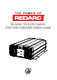
RS Series 12V & 24V Inverters (700/1000/1500/2000/3000W models)
RS SERIES INVERTERS REDARC Pure Sine Wave Inverters produce a pure sine wave output. This means that the power output from a REDARC Pure Sine Wave Inverter is not only the same as the mains supply, it’s often better! WARNINGS & SAFETY INSTRUCTIONS SAVE THESE INSTRUCTIONS - This manual contains IMPORTANT SAFETY INSTRUCTIONS for the REDARC RS series Pure Sine Wave Inverters.
WARNINGS AND SAFETY INSTRUCTIONS 5. 6. 7. 8. 9. 1. 2. 3. 4. 5. 6. 7. 8. Be extra cautious so as to reduce the risk of dropping a metal tool onto a vehicle battery. Doing so might cause the battery to spark or might short-circuit the battery or other electrical parts that may cause an explosion. Remove personal metal items such as rings, bracelets, necklaces, and watches when working with a battery.
CONTENTS Table of Contents Page Warnings and Safety Instructions Contents 1 Introduction 1. Quick Start Guide 2. Specifications 3. Voltage and temperature performance 4. Dimensions 2 User Guide 1. Front Panel Operations 1. Main Switch 2. Indicator LED 3. Function Switch 4. Power Saving Load Adjustment 5. TRC Port (RJ45) 6. AC Output Interface 2. Rear Panel Operations 1. Remote Port (RJ11) 2. Remote Control Green Terminal 3. Chassis Ground 4.
1 INTRODUCTION 1.1 Quick Start Guide 1 Ensure no loads are connected to the Inverters AC Output. 2 Ensure that the Inverter Main Switch is set to the ‘OFF’ position. Ensure all Loads are Disconnected Set Main Switch to ‘OFF’ 4 5 Ensure that the cable is of adequate size and is protected by the correct sized fuse. Connect Chassis Ground Terminal to Negative Input Terminal 3 Connect the DC cables to the Inverters DC Input Terminals.
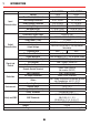
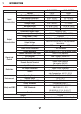
1 INTRODUCTION 1.2 Specifications Input Characteristics Output Characteristics Signal and Control Voltage Max.
1 INTRODUCTION Input Characteristics Output Characteristics Signal and Control Voltage Max.
1 INTRODUCTION Input Characteristics Output Characteristics Signal and Control Voltage Max.
1 INTRODUCTION Input Characteristics Output Characteristics Signal and Control Voltage Max.
1 INTRODUCTION Input Characteristics Output Characteristics Signal and Control Voltage Max.
1 INTRODUCTION 1.3 Voltage and Temperature Performance (3000W) 200% (700W - 2000W) 175% 1 Sec Power (W) 115% 1 Min 100% 1 Sec Continuous 0% 16V 32V 10.5V 21V Voltage (V) 700W - 3000W Figure 1.3.1 - Input Voltage vs. Output Power 10 16.
1 INTRODUCTION 1.4 Dimensions B B E E C A A C DC Input Side D 700/1000 W DC Input Side D 1500/2000/3000 W F F A (mm) B (mm) C (mm) D (mm) E (mm) F(mm) 700W 330 80 132 200 7.0 83 1000W 372 69 196 200 7.0 83 1500W 421 92 196 248 7.0 83 2000W 443 103 196 248 7.0 83 3000W 442 103 196 255 7.
2 USER GUIDE RISK OF ELECTRICAL SHOCK. DO NOT DISASSEMBLE THE INVERTER - THE INTERNAL CIRCUITRY CONTAINS HAZARDOUS VOLTAGES. ATTEMPTING TO SERVICE THE UNIT YOURSELF MAY RESULT IN ELECTRIC SHOCK OR FIRE AND WILL VOID THE UNIT WARRANTY. 2.1 Front Panel Operation D C A B E F Figure 2.1.1 - 700/1000W Models D C A B F E Figure 2.1.2 - 1500/2000W Models D C B A E F Figure 2.1.
2 USER GUIDE 2.1.1 Main Switch A The 3 stage switch is for turning ON or OFF and selecting Remote mode Set the power switch to the “ON” position. The LED will glow GREEN. Set the power switch to the “OFF” position. The inverter will stop and all LEDs will turn off. 2.1.2 Indicator LED B 2.1.2.1 Input Voltage Level LED Status 12V Models 24V Models Red < 11.0V < 22.0V Orange 11.0 ~ 11.5V 22.0 ~ 23.0V Green 11.5 ~ 15.0V 23.0 ~ 30.0V Orange 15.0 ~ 15.5V 30.0 ~ 31.0V Red > 15.5V > 31.
2 USER GUIDE 2.1.2.3 Inverter Status & fault conditions Status LED Status Normal Green Over Current Protection / Over Load Protection (AC output short and overload) Red Under Voltage Protection (Input DC voltage under spec) Red Red Red Recovery Points: 12.5V (12V Models) / 25.0V (24V Models) Over Voltage Protection (Input DC voltage over spec) Red Red Red Red Red Red Recovery Points: 14.5V (12V Models) / 29.
2 USER GUIDE 2.1.3 Function Switch C Default positions shown S1 1 2 ON 3 OFF 4 Figure 2.1.3.1 - Dip Switch ON/OFF Positions 2.1.3.2 Input Voltage Level Dip Switch Function Switch 1 Output Voltage Select Swtich 2 Switch 3 Frequency Select Switch 4 Power Saving mode Select 2.1.3.3 Output Voltage Selection (Switches 1 & 2) Output Voltage Switch 1 Switch 2 200V OFF OFF 220V ON OFF 230V OFF ON 240V ON ON 2.1.3.
2 USER GUIDE 2.1.4 Power Saving Load Adjustment D Figure 2.1.4.1 - Power Saving Load Adjustment The user can adjust the potentiometer to set the input sleep and wake-up thresholds according to the load applied.
2 USER GUIDE 2.1.6 AC Output Interface F 2.1.6.1 700/1000/1500/2000W Models Figure 2.1.6.1 - Standard Australia / New Zealand Socket 2.1.6.2 3000W Models Terminal Wire Colour Line (L) AC Terminal Black Neutral (N) FG (Ground) Wire Size White Green / Yellow or Bare Copper 1.5mm² Min. Ensure the AC output interface cover is replaced after connecting the AC output cable and before turning the unit ON. Ensure the cable is firmly retained by the AC output interface cover.
2 USER GUIDE 2.2 Rear Panel Operation 1 2 4 3 Figure 2.2.1 - 700/1000W Models 1 4 2 3 4 Figure 2.2.2 - 1500/2000W Models 1 2 3 4 4 Figure 2.2.
2 USER GUIDE 2.2.1 Remote Port (RJ11) 1 The RS Series inverter can be used with the REMOTE-RS remote controls via RS-232 communication. To enable use, the main switch on the inverter must be set to the “REMOTE” position. Pin Number Signal Description (1) 1 Reserved -- 2 GND Same Polarity as Battery Negative 3 RXD RS232 RXD 4 TXD RS232 TXD 5 RMT Remote controller panel (positive) 6 VCC Internal power for remote controller 2.2.
2 USER GUIDE Figure 2.2.2.2 - Wiring configurations for Remote Control Green Terminal 2.2.3 Chassis Ground 3 Always connect chassis ground to battery negative. Use 1.5mm² or more. RISK OF ELECTRICAL SHOCK. OPERATION OF THE INVERTER WITHOUT A PROPER GROUND CONNECTION MAY RESULT IN AN ELECTRICAL SAFETY HAZARD. ENSURE PROPER GROUND CONNECTION IS MADE DURING INSTALLATION. FOR FIXED AND/OR TRANSPORTABLE (VEHICLE) INSTALLATIONS, INSTALL ACCORDING TO APPROPRIATE AS/NZS STANDARD. 2.2.
2 USER GUIDE Table 2.2.4.1 - Recommended Cable & Fuse Sizing (12V Install) 12V Inverter 700W 1000W 1500W 2000W Fuse Size (A) 125 175 225 250 Recommended Fuse Mega Mega Mega Mega Cable length Cable Size mm² (AWG) 0 - 1m 27 (3) 54 (O) 85 (OOO) 105 (OOOO) 1 - 2m 27 (3) 54 (O) 85 (OOO) 105 (OOOO) 2 - 3m 34 (2) 68 (OO) 85 (OOO) 105 (OOOO) 3 - 4m 54 (O) x 105 (OOOO) 120 4 - 5m 68 (OO) x 120 x 5 - 6m x x x x Fuse ratings are suitable to these recommended minimum cable sizes.
3 INSTALLATION 3.1 Mounting The power inverter should be used in an environment that meets the following requirements: 1. Dry – Do not allow water to drip on or enter into the inverter. 2. Cool – Ambient air temperature should be between 0°C and 40°C, the cooler the better. 3. Safe – Do not install the inverter in a battery compartment or other areas where volatile fumes may exist, such as fuel storage areas or engine compartments. 4.
3 INSTALLATION 3.3 DC Wiring Connections RISK OF ELECTRICAL SHOCK. BEFORE PROCEEDING, CAREFULLY CHECK THAT THE INVERTER IS NOT CONNECTED TO ANY BATTERIES AND THAT ALL WIRING IS DISCONNECTED FROM ANY ELECTRICAL SOURCES. DO NOT CONNECT THE OUTPUT TERMINALS OF THE INVERTER TO AN INCOMING AC SOURCE. DC supply cables should be kept as short as possible whilst still adhering to the above installation requirements (ideally less than 1.8m / 6ft).
3 INSTALLATION Ensure that all the DC connections are tight - torque to 11.7-13Nm (9-10 ft-lbs). Loose connections could result in overheating and can be a potential hazard. M8 Screw Cable Ring Terminal Figure 3.3.2 - 700/1000W Models M8 Nut Spring Washer Washer Ring Terminal Cable Plastic Cover (Red) Plastic Cover (Black) Figure 3.3.3 - 1500W/2000W/3000W Models Do not operate the inverter with damaged or substandard wiring.
3 INSTALLATION 3.4 AC Safety Grounding Depending on the user scenario, the AC output of the inverter may require a user installed breaker or fuse. The inverter incorporates AC short circuit protection. RCDs may be fitted by a licenced electrician in installations using these inverters. These inverters, when installed according to the instructions in this manual, are categorised as EPB inverters. Neither active, nor neutral is referenced to ground and/or chassis within the inverter.
4 TWO YEAR PRODUCT WARRANTY Over the last three decades our company has established a reputation as the power conversion specialist. A 100% Australian-owned company, we have met the needs of customers in transport and other industries through exciting, innovative thinking.
Free technical assistance! please contact REDARC Electronics 23 Brodie Road North, Lonsdale SA (08) 8322 4848 power@redarc.com.au www.redarc.com.au Copyright © 2017 REDARC Electronics Pty Ltd. All rights reserved. MADE IN TAIWAN www.redarc.com.