
Manual


23
3 INSTALLATION
3.3 DC Wiring Connections
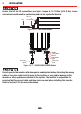
RISK OF ELECTRICAL SHOCK. BEFORE PROCEEDING, CAREFULLY CHECK THAT THE INVERTER
IS NOT CONNECTED TO ANY BATTERIES AND THAT ALL WIRING IS DISCONNECTED FROM
ANY ELECTRICAL SOURCES. DO NOT CONNECT THE OUTPUT TERMINALS OF THE INVERTER
TO AN INCOMING AC SOURCE.
DC supply cables should be kept as short as possible whilst still adhering to the above installation
requirements (ideally less than 1.8m / 6ft). Cables should be of an adequate size to handle the
required currents.
Cables which are not of adequate size (too thin) will result in Voltage drop and poor performance
of the inverter (such as poor surge capability, low-input voltage warnings and shutdowns). As the
supply cable increases in length or reduces in size (gets narrower) the voltage drop will increase.
Batteries are capable of providing very large currents in the case of a short circuit. A fuse must
be installed on the positive supply cable as close as practical to the battery. Failure to do so
provides inadequate protection against fire in the case of a short circuit. Only use high quality
copper cable and keep the cable length short, refer to section 2.2.4 for more information.
Reverse polarity connection will blow the internal fuse and may cause permanent damage
to the inverter.
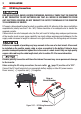
Before making the DC wiring connections, the main switch
A
(page 12) must be set to “OFF”.
Connect the DC input terminals to an appropriate battery supply or other DC power source.
Power source [ + ] is positive and [ - ] is negative.
Battery
Fuse or
Circuit Breaker
+
Figure 3.3.1 - DC Wiring Connections