
Product Manual


2
INSTALLATION INSTRUCTIONS
1. Mount the Smart Start
®
SBI securely in a convenient location near the start battery bank. Do not
mount in direct engine heat.
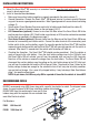
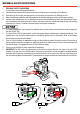
2. Install in the order described below:
• Make sure the auxiliary battery negative is properly grounded to the vehicle chassis (1)
• Ground Connection. Connect the Smart Start
®
SBI ground terminal to chassis ground. Remove
any paint to ensure a good ground connection. Note: A good ground will ensure correct switching
voltage. (2)
• Select correct Circuit Breaker/Fuse sizes and install at battery end of both positive cables (3)
• Connect the cables in the order shown on the next page (4,5,6,7)
• LED Connections (optional). Connect a wire from the Blue wire of the Smart Start
®
SBI to the
positive end of an indicator LED (15mA limited current draw) or LED/resistor combination mounted
on the dash as specifi ed in the diagram on page 3.
• Start Assist Feature (optional). Connect a wire from the Blue wire of the Smart Start
®
SBI to one
terminal of a momentary push button switch. Connect the other terminal of the momentary push
button switch to the auxiliary battery supply. To manually operate the Smart Start
®
SBI, hold the
momentary push button switch and the Smart Start
®
SBI will manually operate until the switch is
released. After about 10 seconds start the vehicle with the button still held on.
• Checking the Operation: The Smart Start
®
SBI should now be operational. Start the vehicle or
apply a charge to the start battery. Once the start battery voltage rises to the ‘ON Volts’ level
the Smart Start
®
SBI will activate, you will hear the solenoid click and see the LED illuminate.
Now turn off the vehicle or remove the charger from the start battery. The Smart Start
®
SBI will
disconnect the auxiliary battery once the voltage on the start battery drops to the OFF Volts level,
you will hear the solenoid click and the LED will go out. Note: The amount of time it takes for the
battery voltage to drop low enough for the solenoid to turn off will vary due to battery condition,
age and state of charge. (For a new, fully charged battery, it may take days). Note: See table on
page 1 for specifi c voltage levels.
NOTE: As per above, the LED may stay ON for a period of time after the vehicle is turned OFF.
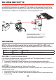
RECOMMENDED FUSES
REDARC recommend using MIDI fuses along with a quality fuse holder to match. The diagram below
shows the construction of a MIDI fuse installation (cables not included).
REDARC MIDI fuse kits containing 4x fuses and 2x fuse
holders along with the required nuts are available from
most Auto Electrical outlets.
Part Numbers:
FK60 60A fuse kit
FK100 100A fuse kit