Classroom Audio System User Manual
TABLE OF CONTENTS SECTION 1: Overview 4 5 6 7 8 9 System Components and Unpacking Optional Components Side Panel Controls and Connections Rear Panel Controls and Connections REDMIKE Controls and Connections Cradle Charger Controls and Connections SECTION 2: Set-up & Use 10 10 11 14 16 17 18 19 20 21 Step 1. Determine Set-up Location 1A. To Set-Up on Table Top 1B. To Set-Up Mounted on a Wall Step 2. Audio Integration Step 3. Connecting the Power Supply Step 4. Charging the REDMIKE Step 5.
5. Warranty, Safety & Specifications OVERVIEW SYSTEM COMPONENTS AND UNPACKING The standard configuration of the REDCAT™ will contain: 2. Setup & Use 3. Optional Accessories 4. Troubleshooting SECTION 1: 1.
Optional equipment which may be part of your REDCAT system: LT-71 LT-71 LightMic and Charger Cable Standard Accessories RX-RC PS-24V-1.75 RMT BA-NH2A27 AC-RMLC BC-RMCC PS-5V-1.
5. Warranty, Safety & Specifications 4. Troubleshooting 3. Optional Accessories SIDE PANEL CONTROLS AND CONNECTIONS 1. COMPUTER VOLUME: Controls the volume level of the audio input from a computer or other device connected to the “computer” input. 2. DVD/VCR VOLUME: Controls the volume level of the audio input from a DVD/VCR or other device connected to the “DVD/VCR” input. 3. ALD VOLUME: Controls the volume level of the audio output to an assisted listening device (ALD). 1. Overview 2. Setup & Use 4.
5. Warranty, Safety & Specifications REAR PANEL CONTROLS AND CONNECTIONS 4. Troublshooting 1. CARRYING INSET: Cutaway grip for moving or carrying the REDCAT. 2. 8-BAND GRAPHIC EQUALIZER: The sliding controls adjust the levels of the various audio frequencies. This allows the installer to properly equalize the system to produce optimum sound quality. 3. Optional Accessories 3. COMPUTER AUDIO INPUT: Plug the 3.5mm cord from computer or other audio source into this jack. 4.
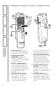
1 4 Slide battery door o p Remove tab before en us e 4. Troubleshooting 5. Warranty, Safety & Specifications REDMIKE CONTROLS AND CONNECTIONS 5 6 3. Optional Accessories 2 2. Setup & Use 3 1. Overview 7 1. POWER BUTTON: Press this button to turn the REDMIKE ON, press again to turn it OFF (mute). 2. POWER/LOW BATTERY INDICATOR: A BLUE light indicates the REDMIKE is on and fully charged. A RED light indicates a charge is needed. 3.
2 3 1. CHARGE INDICATORS: The light glows RED while the REDMIKE is charging. When fully charged, the light will glow GREEN. A blinking RED light indicates that no battery is sensed, (REDMIKE Yellow Protective Tab may not have been completely removed—see page 5, item 4.) A blinking Green LED means a non- Lightspeed battery has been installed (possibly an alkaline battery). 2. DC POWER PORT: Connect the DC power cord here. 3.
5. Warranty, Safety & Specifications 4. Troubleshooting 3. Optional Accessories SECTION 2: SET-UP & USE 1. DETERMINE SET-UP LOCATION The REDCAT is shipped with a table stand connected and ready for use. Alternatively, the table stand can be used as the wall mount bracket. Advantages of either include: Tabletop (recommended): Wall-mount: • Virtually no setup time • More permanent setup • Greater flexibility to move to different locations • Greater security 1. Overview 2. Setup & Use 1A.
Good placement Best placement Good placement 5. Warranty, Safety & Specifications 4. Troublshooting 3. Optional Accessories Next, find a location as far away as possible from the teacher who will be using the mic. The best place is centered on the long wall opposite the teacher. If this is not possible, other good locations are on the wall next to the teacher. Avoid placing the REDCAT on any wall close to where the teacher usually stands to instruct the class.
1. Grip the bottom of the REDCAT where it meets the base. 5. Warranty, Safety & Specifications 2. Setup & Use 3. Optional Accessories 4. Troubleshooting 1B. TO SET-UP MOUNTED ON A WALL CONT’D 1. Overview 2. Slide REDCAT off the base clearing the three guides, then lift clear. 3. Ensure proper orientation of the bracket as shown in the illustration.
7. Holding the REDCAT firmly by the bottom quarter, slide the REDCAT onto the wall bracket as illustrated below. 5. Warranty, Safety & Specifications 4. Troublshooting 6. Attach the bracket to the wall using the mounting screws and drywall anchors (if required). 3. Optional Accessories 5. Mark the wall where the retaining screws will be installed. 2. Setup & Use 4. Place the base/wall bracket against the wall and use a level to confirm the positioning is straight. 1. Overview 1B.
5. Warranty, Safety & Specifications 4. Troubleshooting 2. AUDIO INTEGRATION The next step in setting up your REDCAT system is to connect it to the other elements of your audio system. Audio systems have varying elements – you may have a computer, television, DVD/VCR player, a visual projection system or other devices. In this section you will find instructions on how to connect an external audio device like a TV, VCR, DVD, MP3 or computer directly into the REDCAT. One Possible Set-up Video In 2.
3. With both the REDCAT and audio source power on, adjust the corresponding volume control until the desired level is achieved. NOTE! Be careful to not to set the volume too high, as this can distort the speaker and potentially cause damage. 5. Warranty, Safety & Specifications 4. Troublshooting 3. Optional Accessories 2. Connect a patch cable (not included) from the audio source into the Computer or DVD/VCR input jack on the bottom of the REDCAT. 2. Setup & Use 1.
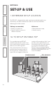
1. Locate the power supply and AC power cord. Connect the AC power cord into the DC power supply. 2. Place the power supply into the REDCAT base as shown. If desired, remove the plastic cover of the included Velcro strip and attach the supply to the Velcro for a more secure fit. 1. Overview 2. Setup & Use 3. Optional Accessories 4. Troubleshooting 5. Warranty, Safety & Specifications 3. CONNECTING THE POWER SUPPLY 3.
REDMIKE incorporates alkaline protection into the microphone design. Always use a Lightspeed rechargeable sensing battery. Replacement AA NiMH batteries may only be purchased through Lightspeed Technologies (part # BA-NH2A27). Do not attempt to charge alkaline batteries. They can overheat and expand creating a significant hazard and damaging the microphone (this is not covered by warranty). 1. Plug power cord into the cradle charger and then plug the AC end into an electrical outlet. 5.
5. Warranty, Safety & Specifications 4. Troubleshooting 3. Optional Accessories 2. Setup & Use 1. Overview 18 5. OPERATING THE REDMIKE Once the REDMIKE is charged, follow these steps to set it up for use. 1. Turn the REDCAT power switch to the ON position. 2. Remove the REDMIKE from the charging cradle and turn it on. The red IR LED (CH. A or CH. B) on the REDCAT will light to indicate a signal is being received. 3.
5. Warranty, Safety & Specifications 6. Additional Adjustments Fine-tuning Audio 250 CD/DVD INPUT 3. Lower the 2K5 and/or 4K sliders if PAGING INPUT a high-pitched ring is present. 4. Lower the 400 and/or 700 sliders if a low-pitched ring is present. R ADJ 1K +10 0 1K4 2K5 4K 6K SENSOR INPUTS SENSOR SHORT -10 5. If feedback is still present, it is likely the volume simply needs to be turned down. 2. Setup & Use 24VDC L 700 1. Overview C POWER L 2.
5. Warranty, Safety & Specifications 4. Troubleshooting 3. Optional Accessories 2. Setup & Use 1. Overview 20 OUTPUT TO ASSISTIVE LISTENING DEVICE (ALD) 1. Turn the ALD (Assistive Listening Device) volume control on the REDMIKE side panel all way the down. 2. Determine the size and type of audio input jack on the device as many manufacturers’ products differ in connector size and shape. The Lightspeed LES-370 Personal FM System requires a 3.5mm to 3.5mm patch cable (part# CAMMC3535, not included). 3.
1. Plug your external audio equipment (for example, laptop), into the input on the REDMIKE labeled “INPUT” using a 3.5mm patch cable. AUDIO OUTPUT AUDIO INPUT 3. Optional Accessories To determine which REDMIKE is set to Channel B, you can look at the switch on the back of the mike or speak into one of the mics and watch which set of LED’s glow on the front panel of the REDCAT (A Volume or B Volume correspond to Channels A or B). 2.
5. Warranty, Safety & Specifications 4. Troubleshooting 3. Optional Accessories 2. Setup & Use OPTIONAL ACCESSORIES OPTIONAL REDMIKE VC (Volume Control) Controls and Connections 1 4 5 6 2 7 3 8 1. POWER /MUTE BUTTON 2. POWER/LOW BATTERY INDICATOR: A BLUE light indicates the REDMIKE VC is on and fully charged. A RED light indicates a charge is needed. 3. BATTERY COMPARTMENT: To open, slide the door downward.
4. Troublshooting Before use, the REDMIKE VC should be charged. See page 17 and follow the same instructions for the REDMIKE. 5. Warranty, Safety & Specifications REDMIKE VC : Charging The teacher can now use the controls on the REDMIKE VC to adjust the volume level from anywhere in the room. The microphone volume control has 4 steps up and 4 steps down from the mid point (9 levels total). 2.
5. Warranty, Safety & Specifications 4. Troubleshooting OPTIONAL LT-71: Controls and Connections 4 LT-71 LT-71 6 2 3 1. Overview 2. Setup & Use 3. Optional Accessories 5 1 1. ON/OFF/MUTE Switch 2. CHANNEL SELECT SWITCH (CH A/B): Use this to choose Channel A or B. If you are using a single microphone, we recommend using Channel A. 3. POWER/CHARGE INDICATOR: A BLUE light indicates the REDMIKE VC is on and fully charged. A RED light indicates a charge is needed. 4.
NOTE: If the system was purchased without a REDMIKE or REDMIKE VC, the LT-71 will utilize the BC-TXLT Wall Charger for charging. Simply plug the wall charger into an AC outlet and plug one of the charging cables into the jack labeled CHARGER on the LT-71. 1. Overview 2. Setup & Use 3. Leave the LT-71 plugged in overnight (8–10 hrs.) to obtain a full charge. 5. Warranty, Safety & Specifications 2. Make sure the cradle charger is plugged into a wall outlet.
5. Warranty, Safety & Specifications 4. Troubleshooting 3. Optional Accessories 2. Setup & Use 1. Overview 26 LT-71: Initial Set-up Once the LT-71 is charged, follow these steps to set it up for use. 1. Turn the REDCAT power switch to the ON position. The RED LED on the switch will glow. 2. Turn on the LT-71 and set the operating channel to “B”. 3. Slip the LT-71 with lanyard around the neck and position the top of the microphone just below the collarbone.
4. Troublshooting 2 4 1. POWER SWITCH: 3. Optional Accessories 5 2. Setup & Use 1 1. Overview 3 5. Warranty, Safety & Specifications REDMIKE Share: Controls and Connections 2. POWER/CHARGE INDICATOR: this light glows blue when turned on and turns off to indicate low battery level. When charging, the light glows red. 3. AUDIO INPUT: plug a laptop, MP3 player or other audio device into this jack to wirelessly transmit the audio signal to be played through the system. 4.
5. Warranty, Safety & Specifications 1. Ensure that the REDMIKE Share is turned OFF. 2. Make sure the cradle charger is plugged into a wall outlet. Connect one end of the charging cable into the jack labeled CHARGER on the bottom of the REDMIKE Share. 1. Overview 2. Setup & Use 3. Optional Accessories 4. Troubleshooting REDMIKE Share: Charging 28 NOTE: If the system was purchased without a REDMIKE or REDMIKE VC, the REDMIKE Share will utilize the BC-TXLT wall charger.
4. While speaking in a normal voice, increase the CH. B VOLUME on the REDCAT level until your voice is barely audible. REMEMBER: This equipment is designed to supplement and distribute the user’s voice so they are able to speak in a conversational tone. Having the volume set too high will result in feedback and listener fatigue. 5. Warranty, Safety & Specifications 4. Troublshooting 3. Grip the barrel in the center section. Avoid covering the infrared emitters just below the microphone grille.
5. Warranty, Safety & Specifications 1. Turn off the second microphone. The iR Media Connector uses the same channel (channel B) as the optional second microphone (REDMIKE, LT-71, or REDMIKE Share). As a result, they cannot be used simultaneously. If you have a second microphone, turn it off before transmitting audio from the iRMC. NOTE: If you adjust the CH B volume on the classroom audio system, you will also be changing the volume for your second microphone.
Video In 3. Optional Accessories Projector Projector 5. Warranty, Safety & Specifications The iRMC is designed to integrate with the REDCAT and multiple audio sources, allowing other instructional technologies to be clearly heard throughout the classroom. 4. Troublshooting OPTIONAL IR MEDIA CONNECTOR AUDIO INTEGRATION Teacher’s Microphone 2. Setup & Use Audio Out VGA Out Audio In Video Out Audio Out iR Media Connector DVD/VCR Audio Out OTHER OPTIONAL ACCESSORIES 1.
5. Warranty, Safety & Specifications 4. Troubleshooting 3. Optional Accessories 2. Setup & Use 1. Overview SECTION 4: TROUBLESHOOTING COMMON PROBLEMS AND SOLUTIONS Note: Most problems are directly related to low battery power. Please run through the “Battery Check” items first. For remaining troubleshooting, use known good, fully-charged batteries. ALL PROBLEMS: Most Problems are related to low battery power. SOLUTION: Battery Check • Confirm batteries are charged each night.
5. Warranty, Safety & Specifications • Speak in a natural voice. A normal conversational speech levelwill provide an adequate signal. It is not necessary to increase the intensity of your voice—the audio system provides adequate amplification (approximately 5 – 10 dB) above ambient room noises. 4. Troubleshooting TIPS TO OBTAIN OPTIMUM AUDIO PERFORMANCE 2. Setup & Use • Recharge batteries each night.
5. Warranty, Safety & Specifications 4. Troubleshooting 3. Optional Accessories 2. Setup & Use 1. Overview SECTION 5: WARRANTY, SAFETY & SPECIFICATIONS FIVE-YEAR LIMITED WARRANTY Lightspeed Infrared Audio Systems and optional accessories are warranted against malfunction due to defect in materials and workmanship for a period of five (5) years from date of purchase. System components will be repaired or replaced at Lightspeed’s option.
Heed all warnings. 4. Follow all instructions. 5. Do not use the apparatus near water. 6. Clean only with dry cloth. 7. Do not block any ventilation openings. Install in accordance with the manufacturer’s instructions. 8. Do not install near any heat sources such as radiators, heat registers, stoves, or other apparatus (including amplifiers) that produce heat. 9. Do not defeat the safety purpose of the polarized or grounding-type plug.
5. Warranty, Safety & Specifications SAFETY WARNINGS AND CERTIFICATIONS 4. Troubleshooting CAUTION RISK OF ELECTRIC SHOCK DO NOT OPEN CAUTION: TO REDUCE THE RISK OF ELECTRIC SHOCK DO NOT REMOVE COVER (OR BACK) NO USER-SERVICEABLE PARTS INSIDE 1. Overview 2. Setup & Use 3.
20 Watts 120 Hz – 13 kHz >77 dB > 73 dB 14” x 22.25” x 3” 18.9” X 7” 8 lbs. RECEIVER SPECIFICATIONS Carrier Frequencies (IR) IR Operating Range Receiver Type Receiver Sensitivity Image and Spurious Rejection 2.06 / 2.54 MHz up to 1600 square feet Superheterodyne 6 μV for 60 dB S/N > 70 dB 5. Warranty, Safety & Specifications Power Output Amplifier Frequency Response Signal-to-Noise Ratio Dynamic Range Overall Dimensions (W x D x H) Table Stand Footprint (W x D) Weight 4.
LIGHTSPEED TECH N O L O G I E S 11509 SW HERMAN R O A D / T U A L AT I N , O R 9 7 0 6 2 TOLL FREE: 800.73 2 . 8 9 9 9 / P H O N E : 5 0 3 . 6 8 4 . 5 5 3 8 / FA X : 5 0 3 . 6 8 4 . 3 1 9 7 LIGHTSPEED-TEK.