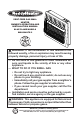
VENT-FREE GAS WALL HEATER OWNER’S OPERATION AND INSTALLATION MANUAL BLUE FLAME MODELS BWH30NLTE-2 WARNING: If the information in this manual is not followed exactly, a fire or explosion may result causing property damage, personal injury or loss of life. — Do not store or use gasoline or other flammable vapors and liquids in the vicinity of this or any other appliance. — WHAT TO DO IF YOU SMELL GAS • Do not try to light any appliance.
TABLE OF CONTENTS Safety......................................................... 3 Qualified Installing Agency......................... 4 Specifications............................................. 5 Product Features........................................ 6 Local Codes............................................... 6 Preparing For Installation........................... 6 Unpacking.................................................. 7 Water Vapor: A By-Product Of Unvented Room Heaters.......................
SAFETY IMPORTANT: Read this owner’s manual carefully and completely before trying to assemble, operate, or service this heater. Improper use of this heater can cause serious injury or death from burns, fire, explosion, electrical shock and carbon monoxide poisoning. NATURAL AND PROPANE/LP GAS: Natural and Propane/LP gas are odorless. An odormaking agent is added to the gas. The odor helps you detect a gas leak. However, the odor added to the gas can fade. Gas may be present even though no odor exists.
SAFETY 1. Do not place Propane/LP supply tank(s) inside any structure. Propane/LP supply tank(s) must be placed outdoors. 2. Heaters with a maximum input over 6,000 Btu/Hr shall not be installed in a bathroom. Heaters with a maximum input over 10,000 Btu/Hr shall not be installed in a bedroom. 3. This heater needs fresh air ventilation to run properly. This heater has an Oxygen Depletion Sensing (ODS) safety shutoff system. The ODS shuts down the heater if not enough fresh air is available.
SPECIFICATIONS Model BWH30NLTE-2 Ignition Piezo Ignitor Gas Type BTU/Hr Input Max. (available) Natural Propane 30,000 30,000 BTU/Hr Input Min. (available) 15,000 24,000 Pressure Regulator Setting 4" W.C. 9" W.C. Inlet Gas Pressure* Max. 9.5" (inches of water) Min. 5" Heater Dimensions (HxWxD) Max. 14" Min. 11" 24.1" x 25.5 x 8.46" Carton Dimensions (HxWxD) 26.18" x 28.15" x 9.84" Heater Weight 27.6 lbs Shipping Weight 31.
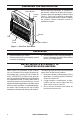
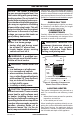
PREPARING FOR INSTALLATION Ignitor Button Control Knob Before beginning assembly or operation of the product, make sure all parts are present. Compare parts with package contents list and Figure 1. If any part is missing or damaged, do not attempt to assemble, install or operate the product. Contact customer service for replacement parts. Burner Grill Front Panel Heater Cabinet Figure 1 - Vent-Free Gas Heater UNPACKING 1. Remove heater from carton. 2.
AIR FOR COMBUSTION AND VENTILATION WARNING: This heater shall not be installed in a confined space or unusually tight construction unless provisions are provided for adequate combustion and ventilation air. Read the following instructions to insure proper fresh air for this and other fuel-burning appliances in your home.
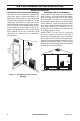
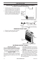
AIR FOR COMBUSTION AND VENTILATION VENTILATION AIR Ventilation Air From Inside Building This fresh air would come from an adjoining unconfined space. When ventilating to an adjoining unconfined space, you must provide two permanent openings: one within 12" of the ceiling and one within 12" of the floor on the wall connecting the two spaces (see options 1 and 2, Figure 2). You can also remove door into adjoining room (see option 3, Figure 2). Follow the National Fuel Gas Code, ANSI Z223.
INSTALLATION NOTICE: This heater is intended for use as supplemental heat. Use this heater along with your primary heating system. Do not install this heater as your primary heat source. If you have a central heating system, you may run system’s circulating blower while using heater. This will help circulate the heat throughout the house. In the event of a power outage, you can use this heater as your primary heat source.
INSTALLATION INSTALLING THERMOSTAT SENSING BULB (OPTIONAL) For Heaters with Blower Installed Only 1. Carefully remove bulb clips with thermostat sensing bulb from the shipping position in the back panel, see Figure 5. 2. Insert bulb clips into 2 rectangular slots beside the shipping location (relocation position). If clips are damaged replace with clips located in the hardware package.
INSTALLATION Marking Screw Locations 1. Tape mounting bracket to wall where heater will be located. Make sure mounting bracket is level. WARNING: Maintain minimum clearances shown in Figure 4, page 9. If you can, provide greater clearances from floor and joining wall. 2. Mark screw locations on wall (see Figure 7). Note: Mark only last hole on each end of mounting bracket. Insert mounting screws through these holes only. 3. Remove tape and mounting bracket from wall. Adjoining Wall 10 1/8" Min.
INSTALLATION Placing Heater On Mounting Bracket 1. Locate two horizontal slots on back panel of heater (see Figure 10). 2. Place heater onto mounting bracket. Slide horizontal slots onto stand-out tabs on mounting bracket.
INSTALLATION GAS SELECTION CAUTION: To avoid gas leakage for the gas not being used at the inlet of regulator, a qualified installer or service technician must use supplied cap. You will notice a color coded plunger on the inside of the regulator. This is normal. When the inlet connection fitting is inserted and tightened, this plunger will be pushed back by the fitting making all of the adjustments for the gas being supplied. DO NOT REMOVE THE PLUNGER. The regulator will not work.
INSTALLATION 2. Apply thread sealant to the threads on a 3/8" NPT brass connection fitting. While pushing in, rotate the fitting clockwise until the threads engage the regulator. After the fitting has been hand tightened into the regulator use a wrench to complete tightening of the fitting. Install additional fitting to connect to the house supply. Fitting supplied by installer, may vary. Use only the cap supplied on the regulator. Do not use an off the shelf pipe plug. This can damage the plunger.
INSTALLATION CONNECTING TO GAS SUPPLY WARNING: A qualified service technician must connect heater to gas supply. Follow all local codes. WARNING: This appliance requires a 3/8" NPT (National Pipe Thread) inlet connection to the pressure regulator. WARNING: For natural gas, Never connect heater to private (non-utility) gas wells. This gas is commonly known as wellhead gas. WARNING: Do not overtighten gas connections. CAUTION: Use only new, black iron or steel pipe.
INSTALLATION Apply pipe joint sealant lightly to male threads. as shown in Figure 17. Pointing the vent down This will prevent excess sealant from going protects it from freezing rain or sleet. into pipe. Excess sealant in pipe could result Install sediment trap in supply line as shown in clogged heater valves. in Figure 16. Place sediment trap where it is The installer must supply an external regula- within reach for cleaning. Place sediment trap tor.
INSTALLATION Test Pressures Equal To or Less Than 1/2 PSIG (3.5 kPa) Gas Valve 1. Close equipment shutoff valve (see Figure 18). Propane/LP 2. Pressurize supply piping system by either Supply Tank using compressed air or opening gas supply valve. 3. Check all joints from gas supply (see Figure 19 or 20) to equipment shutoff valve. Apply a noncorrosive leak detection fluid Equipment Shutoff Valve to all joints. Bubbles forming show a leak. 4. Correct all leaks at once.
OPERATION FOR YOUR SAFETY READ BEFORE LIGHTING WARNING: If you do not follow these instructions exactly, a fire or explosion may result causing property damage, personal injury or loss of life. A. This appliance has a pilot which must be lighted by hand. When lighting the pilot, follow these instructions exactly. B. BEFORE LIGHTING smell all around the appliance area for gas. Be sure to smell next to the floor because some gas is heavier than air and will settle on the floor.
OPERATION 7. Keep control knob pressed in for 30 seconds after lighting pilot. After 30 seconds, release control knob. If control knob does not pop up when released, contact a qualified service technician or gas supplier for repairs. Note: If pilot goes out, repeat steps 2 through 6. This heater has a safety interlock system. Wait one (1) minute before lighting pilot again. 8. Turn control knob counterclockwise to desired heating level. The main burner should light.
ELECTRICAL CONNECTION FOR BLOWER KIT Do not use this heater if any part of it has been under water. Immediately call a qualified service technician to inspect the heater and replace any part of the electrical system which has been under water. GROUNDING INSTRUCTIONS This heater is for use on 120 volts. The cord has a plug as shown at A in Figure 23. An adapter as shown at C is available for connecting three-blade grounding-type plugs to two-slot receptacles.
INSPECTING BURNERS IMPORTANT: Owner’s should check pilot flame pattern and burner flame pattern often. Incorrect flame patterns indicate the need for cleaning (see Care and Maintenance, page 22) or service. WARNING: Only a qualified service person should service and repair heater. This includes maintenance requiring replacement or alteration of components. PILOT FLAME PATTERN Figure 24 shows a correct pilot flame pattern. Figure 25 shows an incorrect pilot flame pattern.
CARE AND MAINTENANCE WARNING: Turn off heater and let cool before servicing. CAUTION: You must keep control areas, burner, and circulating air passageways of heater clean. Inspect these areas of heater before each use. Have heater inspected yearly by a qualified service technician. Heater may need more frequent cleaning due to excessive lint from carpeting, bedding material, pet hair, etc. WARNING: Failure to keep the primary air opening(s) of the burner(s) clean may result in sooting and property damage.
CARE AND MAINTENANCE MAINTENANCE OF BLOWER MOTOR (IF EQUIPPED) Always disconnect the appliance from the main power supply and allow it to cool before any servicing operation. The motors used on the fan heater and flame blower are pre-lubricated for extended bearing life and require no further lubrication. However, periodic cleaning/vacuuming of the appliance around the air intake and exhaust, as well as the fan heater is recommended.
TROUBLESHOOTING Only a qualified installer should bypass the pressure switch. Remove front panel of heater (see page 10). Locate the gas regulator. To bypass the pressure switch locate the set screw on the regulator. Use a small flat bladed screw driver to turn the set screw counterclockwise 2 turns. This will bypass the pressure switch function. The entire gas delivery piping including connections inside the heater should be leak tested by the qualified installer.
TROUBLESHOOTING Problem Possible Cause Corrective Action ODS/pilot lights but flame 1. Control knob is not fully 1. Press in control knob fully. goes out when control pressed in. knob is released. 2. Control knob is not pressed 2. After ODS/pilot lights, keep in long enough. control knob pressed in 30 seconds. 3. Equipment shutoff valve is 3. Fully open equipment shutoff not fully open. valve. 4. Thermocouple connection is 4. Hand tighten until snug, and loose at control valve.
TROUBLESHOOTING Problem Possible Cause Corrective Action Heater produces a whis- 1. Turning control knob to high 1. Turn control knob to low (1) tling noise when burner (5) position when burner is position and let warm up for is lit. cold. a minute. 2. Air in gas line. 2. Operate burner until air is removed from line. Have gas line checked by local gas supplier. 3. Air passageways on heater 3 Observe minimum installation are blocked. clearances (Figure 4, page 9). 4.
REPLACEMENT PARTS Note: Use only original replacement parts. This will protect your warranty coverage for parts replaced under warranty. PARTS UNDER WARRANTY PARTS NOT UNDER WARRANTY Call Customer Service toll free at 1-800-229-5647 to order parts under warranty.
PARTS MODEL BWH30NLTE-2 2 17 3 10 11 4 1 5 12 12 6 7 8 9 13 15 16 14 28 www.sureheat.
PARTS MODEL BWH30NLTE-2 This list contains replaceable parts for your heater. When ordering replacement parts, follow the instructions listed under Replacement Parts on page 27 of this manual.
NOTES ________________________________________________________________ ________________________________________________________________ ________________________________________________________________ ________________________________________________________________ ________________________________________________________________ ________________________________________________________________ ________________________________________________________________ ___________________________________________________
NOTES ________________________________________________________________ ________________________________________________________________ ________________________________________________________________ ________________________________________________________________ ________________________________________________________________ ________________________________________________________________ ________________________________________________________________ ___________________________________________________
WARRANTY KEEP THIS WARRANTY Model ________________________________ Serial No. _____________________________ Date Purchased ________________________ Keep receipt for warranty verification. IMPORTANT: We urge you to fill out your warranty information above. Complete with the entire serial number which can be found on the rating plate. Retain this manual for future reference. Always specify model and serial numbers when communicating with customer service.