
Installation Guide


www.sureheat.com
200305-01C20
ELECTRICAL CONNECTION
FOR BLOWER KIT
Do not use this heater if any
part of it has been under water.
Immediately call a qualied ser-
vice technician to inspect the
heater and replace any part of
the electrical system which has
been under water.
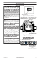
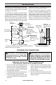
GROUNDING INSTRUCTIONS
This heater is for use on 120 volts. The cord
has a plug as shown at A in Figure 23. An
adapter as shown at C is available for con-
necting three-blade grounding-type plugs to
two-slot receptacles. The green grounding
lug extending from the adapter must be
connected to a permanent ground such as
a properly grounded outlet box. The adapter
should not be used if a three-slot grounded
receptacle is available.
Grounding Pin
Grounding Means
Metal Screw
Cover of
Grounded
Outlet Box
A
B
C
Adapter
Figure 23 - Grounded Electrical Outlet
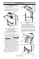
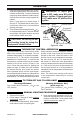
ELECTRICAL WIRING
Any electrical re-wiring of this appliance must
be done by a qualied electrician. This wiring
must be done in accordance with local codes
and/or in Canada with the current CSA C22.1
Canadian Electrical Code, and for US instal-
lations, the National Electrical Code ANSI/
NFPA NO 70.
WARNING: If repairing or
replacing any electrical compo-
nent or wiring, the original wire
routing, color coding and secur-
ing locations must be followed.
CAUTION: Label all wires
prior to disconnection when
servicing controls. Wiring errors
can cause improper and danger-
ous operation.
WARNING: Never attempt to
service heater while it is plugged
in, operating, or hot. Burns and
electrical shock could result.
Only a qualied service person
should service or repair heater.
Verify proper operation after servicing. If any
of the original wire as supplied with the appli-
ance must be replaced, it must be replaced
with a wire of at least a 105º C temperature
rating.
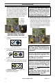
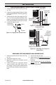
Motor
Black
Green
White
Switch
Thermostat Switch
AUTO
O
MAN
(Sold
Separately)
FAN OPERATION
To operate the manual unit, turn ON/OFF
switch to the ON position. To operate the
Automatic unit, turn AUTO/O/MAN switch to
the desired position. MAN position will remain
constantly on. AUTO position will be controlled
by the sensor on the fan blower unit. The sen-
sor will be activated when the temperature of
the sensor head reaches the set point of the
switch after the heater is started. To stop the
operation, turn the switch to the O position.