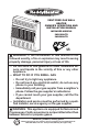
VENT-FREE GAS WALL HEATER OWNER’S OPERATION AND INSTALLATION MANUAL INFRARED MODELS IWH16NLTD IWH26NLTD PFS ® US WARNING: If the information in this manual is not followed exactly, a fire or explosion may result causing property damage, personal injury or loss of life. — Do not store or use gasoline or other flammable vapors and liquids in the vicinity of this or any other appliance. — WHAT TO DO IF YOU SMELL GAS • Do not try to light any appliance.
TABLE OF CONTENTS Safety......................................................... 3 Specifications............................................. 4 Qualified Installing Agency......................... 5 Product Features........................................ 5 Local Codes............................................... 5 Preparing For Installation........................... 6 Unpacking.................................................. 6 Water Vapor: A By-Product Of Unvented Room Heaters.......................
SAFETY IMPORTANT: Read this owner’s manual carefully and completely before trying to assemble, operate, or service this heater. Improper use of this heater can cause serious injury or death from burns, fire, explosion, electrical shock and carbon monoxide poisoning. Only a qualified installer, service agent, or local gas supplier may install and service this product. WARNING: Keep the appliance area clear and free from combustible materials, gasoline, and other flammable vapors and liquids.
SAFETY 1. Do not place Propane/LP supply tank(s) inside any structure. Propane/LP supply tank(s) must be placed outdoors. 2. Heaters 10,000 Btu/Hr or more shall not be installed in a bedroom or bathroom. 3. This heater needs fresh air ventilation to run properly. This heater has an Oxygen Depletion Sensing (ODS) safety shutoff system. The ODS shuts down the heater if not enough fresh air is available. See Air for Combustion and Ventilation, page 7. If heater keeps shutting off, see Troubleshooting, page 23.
QUALIFIED INSTALLING AGENCY Only a qualified agency should install and replace gas piping, gas utilization equipment or accessories, and repair and equipment servicing.
PREPARING FOR INSTALLATION Before beginning assembly or operation of the product, make sure all parts are present. Compare parts with package contents list. If any part is missing or damaged, do not attempt to assemble, install or operate the product. Contact customer service for replacement parts. Ignitor Control Knob Button Grill Burner Front Panel Base (Optional) Heater Cabinet Figure 1 - Vent-Free Gas Heater UNPACKING 1. Remove heater from carton. 2.
AIR FOR COMBUSTION AND VENTILATION WARNING: This heater shall not be installed in a confined space or unusually tight construction unless provisions are provided for adequate combustion and ventilation air. Read the following instructions to insure proper fresh air for this and other fuel-burning appliances in your home.
AIR FOR COMBUSTION AND VENTILATION VENTILATION AIR Ventilation Air From Inside Building This fresh air would come from an adjoining unconfined space. When ventilating to an adjoining unconfined space, you must provide two permanent openings: one within 12" of the ceiling and one within 12" of the floor on the wall connecting the two spaces (see options 1 and 2, Figure 2). You can also remove door into adjoining room (see option 3, Figure 2). Follow the National Fuel Gas Code, ANSI Z223.
INSTALLATION NOTICE: This heater is intended for use as supplemental heat. Use this heater along with your primary heating system. Do not install this heater as your primary heat source. If you have a central heating system, you may run system’s circulating blower while using heater. This will help circulate the heat throughout the house. In the event of a power outage, you can use this heater as your primary heat source.
INSTALLATION LOCATING HEATER This heater is designed to be mounted on a wall. For convenience and efficiency, install heater: 1. Where there is easy access for operation, inspection, and service. 2. In the coldest part of room. FASTENING HEATER TO WALL Mounting Bracket The mounting bracket is located on back panel of heater (see Figure 5). It has been taped there for shipping. Remove mounting bracket from back panel.
INSTALLATION Attaching Mounting Bracket To Wall Note: Wall anchors, mounting screws, and spacers are in hardware package. The hardware package is provided with heater. Attaching to Wall Stud Method For attaching mounting bracket to wall studs: 1. Drill holes at marked locations using 9/64" drill bit. 2. Place mounting bracket onto wall. Line up last hole on each end of bracket with holes drilled in wall. 3. Insert mounting screws through bracket and into wall studs. 4.
INSTALLATION Installing Bottom Mounting Bracket 1. Install bottom bracket to heater bottom with two screws. It may be more convenient to remove heater from wall bracket to attach. 2. Place heater on wall mounting bracket. 3. Mark screw locations on wall. 4. Remove heater from mounting bracket. 5. If installing bottom mounting screws into hollow or solid wall, install wall anchors. FrontFollow View 10,000 steps 1 through 4 under Attaching To Btu Wall Anchor Method, page 11.
INSTALLATION GAS SELECTION CAUTION: To avoid gas leakage for the gas not being used at the inlet of regulator, a qualified installer or service technician must use supplied cap. You will notice a color coded plunger on the inside of the regulator. This is normal. When the inlet connection fitting is inserted and tightened, this plunger will be pushed back by the fitting making all of the adjustments for the gas being supplied. DO NOT REMOVE THE PLUNGER. The regulator will not work.
INSTALLATION 2. Apply thread sealant to the threads on the connection fitting. While pushing in, rotate the fitting clockwise until the threads engage the regulator. After the fitting has been hand tightened into the regulator use a wrench to complete tightening of the fitting. Install additional fitting to connect to the house supply. FOR NATURAL GAS (NG) INSTALLATION: YELLOW 1. Remove the blue dust cover from the regulator. Use only the cap supplied on the regulator.
INSTALLATION CONNECTING TO GAS SUPPLY WARNING: A qualified service technician must connect heater to gas supply. Follow all local codes. WARNING: This appliance requires a 3/8" NPT (National Pipe Thread) inlet connection to the pressure regulator. WARNING: For natural gas, Never connect heater to private (non-utility) gas wells. This gas is commonly known as wellhead gas. WARNING: Do not overtighten gas connections. CAUTION: Use only new, black iron or steel pipe.
INSTALLATION Apply pipe joint sealant lightly to male threads. This will prevent excess sealant from going into pipe. Excess sealant in pipe could result in clogged heater valves. For propane/LP gas, the installer must supply an external regulator. The external regulator will reduce incoming gas pressure. You must reduce incoming gas pressure to between 11" and 14" of water. If you do not reduce incoming gas pressure, heater regulator damage could occur.
INSTALLATION 4. Check all joints of gas supply piping system. Apply a noncorrosive leak detection fluid to all joints. If bubbles form, there may be a leak. 5. Correct all leaks at once. 6. Reconnect heater and equipment shutoff valve to gas supply. Check reconnected fittings for leaks. Test Pressures Equal To or Less Than 1/2 PSIG (3.5 kPa) 1. Close equipment shutoff valve (see Figure 17). 2.
OPERATION FOR YOUR SAFETY READ BEFORE LIGHTING WARNING: If you do not follow these instructions exactly, a fire or explosion may result causing property damage, personal injury or loss of life. A. This appliance has a pilot which must be lighted by hand. When lighting the pilot, follow these instructions exactly. B. BEFORE LIGHTING smell all around the appliance area for gas. Be sure to smell next to the floor because some gas is heavier than air and will settle on the floor.
OPERATION Note: If pilot goes out, repeat steps 3 through 7. This heater has a safety interlock system. Wait one (1) minute before lighting pilot again. 8. Turn control knob counterclockwise to desired heating level. The main burner should light. Set control knob to any heat level between 1 and 5. CAUTION: Do not try to adjust heating levels by using the equipment shutoff valve. WARNING: If input gas type is NG, make sure NG pilot burner ignites. If input gas type is LP, make sure LP pilot burner ignites.
ELECTRICAL CONNECTION FOR HEATERS EQUIPPED WITH A BLOWER Do not use this heater if any part of it has been under water. Immediately call a qualified service technician to inspect the heater and replace any part of the electrical system which has been under water. GROUNDING INSTRUCTIONS This heater is for use on 120 volts. The cord has a plug as shown at A in Figure 23. An adapter as shown at C is available for connecting three-blade grounding-type plugs to two-slot receptacles.
INSPECTING HEATER IMPORTANT: Owner’s should check pilot flame pattern and burner flame pattern often. Incorrect flame patterns indicate the need for cleaning (see Care and Maintenance, page 22) or service. WARNING: Only a qualified service person should service and repair heater. This includes maintenance requiring replacement or alteration of components. PILOT FLAME PATTERN Figure 24 shows a correct pilot flame pattern. Figure 25 shows an incorrect pilot flame pattern.
CARE AND MAINTENANCE WARNING: Turn off heater and let cool before servicing. CAUTION: You must keep control areas, burner, and circulating air passageways of heater clean. Inspect these areas of heater before each use. Have heater inspected yearly by a qualified service technician. Heater may need more frequent cleaning due to excessive lint from carpeting, bedding material, pet hair, etc. WARNING: Failure to keep the primary air opening(s) of the burner(s) clean may result in sooting and property damage.
TROUBLESHOOTING WARNING: If you smell gas: • Shut off gas supply. • Do not try to light any appliance. • Do not touch any electrical switch; do not use any phone in your building. • Immediately call your gas supplier from a neighbor’s phone. Follow the gas supplier’s instructions. • If you cannot reach your gas supplier, call the fire department. WARNING: Only a qualified service technician should service and repair heater. Make sure that power is turned off before proceeding.
TROUBLESHOOTING Problem Possible Cause Corrective Action When ignitor button is 1. Ignitor electrode is posi- 1. Replace pilot assembly. pressed in, there is no tioned wrong. Ignitor elecspark at ODS/pilot. trode is broken. 2. Ignitor electrode is not con- 2. Replace ignitor cable. nected to ignitor cable. 3. Ignitor cable is pinched or 3. Free ignitor cable if pinched wet. by any metal or tubing. Keep ignitor cable dry. 4 Broken ignitor cable. 4. Replace ignitor cable. 5. Bad piezo ignitor. 5.
TROUBLESHOOTING Problem Possible Cause Corrective Action Burner(s) does not light 1. Burner orifice is clogged. after ODS/pilot is lit. 1. Clean burner orifice (see Care and Maintenance, page 22) or replace burner orifice. 2. Burner orifice diameter is too 2. Replace burner orifice. small. 3. Inlet gas pressure is too low. 3. Contact local gas supplier. Delayed ignition of 1. Manifold pressure is too low. 1. Contact local gas supplier. burner(s). 2. Burner orifice is clogged. 2.
TROUBLESHOOTING Problem Possible Cause Corrective Action Heater produces a click- 1. Metal is expanding while 1. This is common with most ing/ticking noise just after heating or contracting while heaters. If noise is excesburner is lit or shut off. cooling. sive, contact qualified service technician. White powder residue 1. When heated, the vapors 1. Turn heater off when using forming within burner from furniture polish, wax, furniture polish, wax, carpet box or on adjacent walls carpet cleaners, etc.
REPLACEMENT PARTS Note: Use only original replacement parts. This will protect your warranty coverage for parts replaced under warranty. PARTS UNDER WARRANTY Call Customer Service toll free at 1-800-229-5647 to order parts under warranty.
PARTS MODEL IWH16NLTD 12 1 11 9 2 5 6 3 7 10 8 4 13 14 28 www.sureheat.
PARTS MODEL IWH16NLTD This list contains replaceable parts for your heater. When ordering replacement parts, follow the instructions listed under Replacement Parts on page 27 of this manual.
PARTS MODEL IWH26NLTD 12 1 11 9 2 5 6 7 3 10 8 4 13 14 30 www.sureheat.
PARTS MODEL IWH26NLTD This list contains replaceable parts for your heater. When ordering replacement parts, follow the instructions listed under Replacement Parts on page 27 of this manual.
WARRANTY KEEP THIS WARRANTY Model ________________________________ Serial No. _____________________________ Date Purchased ________________________ Keep receipt for warranty verification. IMPORTANT: We urge you to fill out your warranty information above. Complete with the entire serial number which can be found on the rating plate. Retain this manual for future reference. Always specify model and serial numbers when communicating with customer service.
CALENTADOR DE GAS DE PARED SIN VENTILAS MANUAL DE FUNCIONAMIENTO E INSTALACIÓN DEL PROPIETARIO INFRARROJO MODELOS IWH16NLTD IWH26NLTD PFS ® US ADVERTENCIA: Este aparato está equipado para funcionar con gas (natural y propano). No se permite convertir más que a gas natural o gas propano.
TABLA DE CONTENIDOS Seguridad................................................. 35 Especificaciones....................................... 37 Agencia de Instalación Calificada............ 37 Características del Producto.................... 38 Normas Locales....................................... 38 Preparación Para la Instalación............... 39 Desempaque............................................ 39 Vapor De Agua: Un Producto Derivado de Los Calentadores de Habitación Sin Ventilación....................
SEGURIDAD IMPORTANTE: Lea este manual del propietario cuidadosa y completamente antes de intentar ensamblar, operar o dar servicio a este calentador. El uso inadecuado de este calentador puede causar daños a la propiedad, lesiones graves o la muerte por quemaduras, incendio, explosión, electrocución e intoxicación con monóxido de carbono. No seguir estas instrucciones anula la garantía.
SEGURIDAD ADVERTENCIA: Este calentador alcanza temperaturas muy altas cuando el calentador está en funcionamiento. Mantenga a niños y adultos alejados de las superficies calientes para evitar quemaduras o que la ropa se encienda. El calentador permanecerá caliente durante algún tiempo después de que se ha apagado. Permita que la superficie se enfríe antes de tocarla. ADVERTENCIA: No coloque ropa ni otros materiales inflamables sobre el aparato ni cerca del mismo.
ESPECIFICACIONES Encendido MODELO IWH16NLTD Piezoeléctrico IWH26NLTD Piezoeléctrico Tipo de gas Con gas natural Con gas natural BTU (disponible) 20,000 30,000 6" de c.a. 6" de c.a. Máximo 10.5" de c.a. Máximo 10.5" de c.a. Mínimo 7" de c.a. Mínimo 7" de c.a. Con gas propano Con gas propano Ajuste del regulador de presión: Presión del gas de entrada* (pulg. de agua) Tipo de gas BTU (disponible) Ajuste del regulador de presión: Presión del gas de entrada* (pulg.
CARACTERÍSTICAS DEL PRODUCTO PILOTO DE SEGURIDAD PIEZO SISTEMA DE ENCENDIDO El calentador posee un piloto que cuenta con un sistema de apagado de seguridad por medio de un sensor de agotamiento de oxígeno (ODS). El sensor de agotamiento de oxígeno del piloto apaga el calentador si no hay suficiente cantidad de aire fresco. Este calentador está equipado con un encendedor piezoeléctrico. este sistema no requiere de fósforos, baterías u otras fuentes a encender el calentador.
PREPARACIÓN PARA LA INSTALACIÓN Antes de ensamblar u operar el producto, asegúrese de tener todas las piezas. Compare las piezas con la lista del contenido del paquete. Si hay piezas dañadas o si faltan piezas, no intente armar, instalar ni usar el producto. Póngase en contacto con el servicio al cliente para obtener piezas de repuesto. Rejilla Botón de encendido Perilla de control Quemador Panel anterior Base (opcional) Gabinete del calentador Figura 1 - Calentador de gas sin ventilación DESEMPAQUE 1.
AIRE PARA COMBUSTIÓN Y VENTILACIÓN ADVERTENCIA: Este calentador no debe instalarse en un espacio confinado ni en una construcción inusualmente sellada, a menos que se hayan tomado las medidas necesarias para proporcionar el aire adecuado para la combustión y la ventilación. Lea las instrucciones siguientes para asegurarse de que su hogar cuente con la cantidad adecuada de aire fresco para éste y otros aparatos que queman combustible.
AIRE PARA COMBUSTIÓN Y VENTILACIÓN AIRE PARA VENTILACIÓN Aire del interior de la construcción para ventilación Este aire fresco viene de un espacio adyacente no confinado. Cuando se ventila mediante 30.5 cm un espacio adyacente no confinado, debe (12") haber dos aberturas permanentes en la pared que está entre los dos espacios: una abertura 30.4 cm (12") del techo y otra 30.
INSTALACIÓN AVISO: Este calentador está diseñado para utilizarse como calefacción adicional. Use este calentador junto con su sistema de calefacción principal. No instale este calentador como fuente de calefacción principal. Si tiene un sistema de calefacción central, puede activar el ventilador de circulación del sistema mientras utiliza el calentador. Esto ayudará a que el calor circule por toda la casa.
INSTALACIÓN DISTANCIA DE SEPARACIÓN DE COMBUSTIBLES COLOCACIÓN DEL CALENTADOR EN LA PARED Siga con atención las siguientes instrucciones. Este calentador es una unidad de montaje en la pared diseñada para apoyarse directamente sobre el suelo o una base de repisa. Soporte de montaje El soporte de montaje se encuentra en el panel posterior del calentador (consulte la Figura 5). Se colocó con cinta en ese lugar para el transporte. Retire el soporte de montaje del panel posterior.
INSTALACIÓN Métodos para fijar el soporte de montaje a la pared Use únicamente el último orificio de cada extremo del soporte de montaje para fijarlo a la pared. Fije el soporte de montaje a la pared mediante una de las dos maneras siguientes: Fijación a viga de pared: este método proporciona la sujeción más firme. Inserte los tornillos de montaje en el soporte de montaje y en las vigas de pared.
INSTALACIÓN 2. Doble el anclaje de pared como se muestra en la figura 8. 3. Inserte el anclaje de pared (las alas primero) en el orificio. Golpee suavemente el anclaje para introducirlo en la pared. 4. Para paredes delgadas, de 1.3 cm (1/2") o menos, inserte la llave roja en el anclaje de pared. Empuje la llave roja para que abra las alas de anclaje (consulte le Figura 9). IMPORTANTE: ¡no golpee la llave con un martillo! Para paredes gruesas, de más de 1.
INSTALACIÓN 6. Vuelva a colocar el calentador en el soporte de montaje. 7. Coloque los separadores entre los orificios de montaje inferiores y el anclaje de pared o el orificio que perforó. 8. Sostenga el separador en su sitio con una mano. Con la otra mano, inserte el tornillo de montaje a través del orificio inferior de montaje y del separador. Coloque la punta del tornillo en la abertura del anclaje de Front View pared o del orificio que perforó. 10,000 Btu 9.
INSTALACIÓN SELECCIÓN DE GAS LPG PRECAUCIÓN: Dos instalaciones de líneas de gas, al mismo tiempo están prohibidos. INLET GAS PRESSURE MAX 1/2 PSIG (3.5 KPA) NG Este aparato viene ajustado de fábrica para gas propano/ LP. No se requieren cambios para la conexión a propano/ LP. Sólo un instalador o técnico de servicio calificado puede realizar la selección de gas y la conexión al suministro de gas.
INSTALACIÓN 2. Aplique sellador de roscas a las roscas en el accesorio de conexión. Mientras presiona, gire hacia la derecha el ajuste hasta que las roscas se acoplan al regulador. Después de la instalación se ha apretado sido parte en el regulador con una llave para completar endurecimiento del accesorio. Instale accesorio adicional para conectar al suministro de la casa. Utilice solamente el tapón suministrado en el regulador. No utilice un fuera el tapón del tubo estante. Esto puede dañar el émbolo.
INSTALACIÓN CONEXIÓN AL SUMINISTRO DE GAS ADVERTENCIA: Una persona de servicio capacitada debe conectar el calentador al suministro de gas. Siga todas las normas locales. ADVERTENCIA: Este aparato requiere una conexión de entrada tipo NPT (rosca de tubería nacional) de 3/8" al regulador de presión. ADVERTENCIA: Para gas natural, nunca conecte el calentador a pozos de gas privados (que no sean de servicio público). Este gas se conoce comúnmente como gas de pozo.
INSTALACIÓN Antes de instalar el calentador, asegúrese de tener los elementos que se indican a continuación.
INSTALACIÓN REVISIÓN DE LAS CONEXIONES DE GAS ADVERTENCIA: Después de instalar el calentador o de darle servicio, pruebe todas las conexiones y tubos de gas de la unidad, tanto internas como externas, en busca de fugas. Repare todas las fugas inmediatamente. ADVERTENCIA: Nunca use una llama al descubierto para verificar si hay fugas. Aplique líquido no corrosivo para detectar fugas en todas las uniones. La formación de burbujas indicará una fuga. Repare todas las fugas inmediatamente.
INSTALACIÓN Comprobación de la presión de las conexiones de gas del calentador 1. Abra la válvula de cierre del equipo (consulte la figura 17, página 51). 2. Si usa gas natural, abra la válvula principal de gas ubicada en el medidor de gas o cerca de éste. Si usa propano o gas LP, abra la válvula de suministro de propano o gas LP. 3. Compruebe que la perilla de control del calentador esté en la posición OFF (apagado). 4.
FUNCIONAMIENTO INSTRUCCIONES DE ENCENDIDO 1. ¡ALTO! Lea la información de seguridad en la página 52. 2. Asegúrese de que la válvula de cierre del equipo esté totalmente abierta. 3. Gire la perilla de control en dirección de la manecillas del reloj hasta la posición OFF (apagado). 4. Espere cinco minutos a que se disipe el gas. Luego, compruebe que no huela a gas, incluso cerca del piso. Si percibe olor a gas, ¡DETÉNGASE! Siga el punto “B” en la información de seguridaden la página 52.
FUNCIONAMIENTO IWH16NLTD IWH26NLTD Quemadores de ALTA Perilla de control Quemadors apagado Figura 21 - Patrón del quemador FUNCIONAMIENTO DEL CONTROL CON TERMOSTATO El control termostático utilizado en este modelo difiere de termostatos estándar. Usted establece termostatos estándar a una temperatura específica, como 72 grados. El termostato utilizado en este calentador detecta la temperatura ambiente. A veces la habitación puede superar la temperatura establecida. Si es así, el quemador se apagará.
CONEXIÓN ELÉCTRICA PARA CALENTADORES EQUIPADO CON UN VENTILADOR No utilice este calentador si alguna de sus piezas estuvo sumergida en agua. Llame de inmediato a un técnico en mantenimiento calificado a fin de que inspeccione la chimenea y remplace cualquier pieza del sistema eléctrico que haya estado bajo agua. INSTRUCCIONES DE CONEXIÓN A TIERRA Este calentador fue diseñado para su uso con 120 voltios. El cable tiene un enchufe, como se muestra en la Figura 23.
INSPECCIÓN DEL CALENTADOR IMPORTANTE: El propietario debe revisar frecuentemente los patrones de la llama del piloto y de la llama del quemador. Patrones de llama incorrectos indican la necesidad de limpieza o servicio de mantenimiento (consulte Cuidado y mantenimiento, página 57). ADVERTENCIA: Sólo una persona de servicio capacitada debe repararlo o darle servicio. Esto incluye el mantenimiento requerido, refacciones o alteración de componentes.
CUIDADO Y MANTENIMIENTO ADVERTENCIA: Apague el calentador y deje que se enfríe antes de darle mantenimiento. PRECAUCIÓN: Debe mantener limpias las áreas de control, el quemador y las vias de circulación de aire del calentador. Inspeccione estas áreas del calentador antes de cada uso. Haga que una persona de servicio calificada inspeccione el calentador una vez al año.
SOLUCIÓN DE PROBLEMAS ADVERTENCIA: Si percibe olor a gas • Cierre el suministro de gas. • No intente encender ningún aparato. • No toque ningún interruptor eléctrico; no use ningún teléfono en el edificio. • Llame inmediatamente a su proveedor de gas desde el teléfono de algún vecino. Siga las instrucciones del proveedor de gas. • Si no puede localizar al proveedor de gas, llame al departamento de bomberos. ADVERTENCIA: Sólo una persona de servicio capacitada debe reparar la calentador y darle servicio.
SOLUCIÓN DE PROBLEMAS Problema Causa Posible Acción correctiva Cuando se presiona el 1. Electrodo de encendido 1. Remplace el electrodo del botón del encendedor, no está mal colocado. Electroencendedor. hay chispa en el piloto/ do de encendido está roto. ODS. 2. El electrodo del encende- 2. Remplace el cable del encendor no está conectado al dedor. cable del encendedor. 3. El cable del encendedor 3. Libere el cable del encendedor está comprimido o mojado. si algún metal o tubería lo está comprimiendo.
SOLUCIÓN DE PROBLEMAS Problema Causa Posible Acción correctiva El piloto/ODS se en- 1. La perilla de control no está 1. Presione la perilla de control ciende pero la llama se presionada completamente. completamente. extingue cuando la perilla 2. La perilla de control no se 2. Después de que el piloto/ODS de control se suelta. presionó durante el tiempo se encienda, mantenga la suficiente. perilla de control presionada durante 30 segundos. 3. La válvula de cierre del 3.
SOLUCIÓN DE PROBLEMAS Problema Causa Posible Acción correctiva Llamas amarillas alta 1. No hay suficiente aire. durante la combustión en el quemador. 1. Revise el quemador en busca de polvo y residuos. Si los hay, limpie el quemador (consulte Cuidado y mantenimiento, en la página 57). 2. El regulador de gas está 2. Remplace el regulador de gas. defectuoso. 3. La entrada de la presión de 3. Contacte a su proveedor local gas es demasiado baja. de gas. Hay olor a gas durante la 1.
SOLUCIÓN DE PROBLEMAS Problema Causa Posible El calentador produce olores no deseados. Acción correctiva 1. En el calentador se están 1. Abra la ventana para ventilar quemado vapores provela habitación. Deje de utilizar nientes de pintura, fijador los productos que ocasionan para el cabello, pegamentos, el olor mientras el calentador productos de limpieza, proesté funcionando. ductos químicos, alfombras nuevas, etc. (Consulte la nota IMPORTANTE pagina 58). 2. Fugas de gas. Consulte la 2.
PIEZAS DE REPUESTO Nota: use sólo piezas de repuesto originales. Esto protegerá la cobertura de su garantía para partes remplazadas bajo la garantía. PIEZAS CON Llame al número de servicio al cliente al 1-800-229-5647 para solicitar piezas en garantía.
PIEZAS MODELO IWH16NLTD 12 1 11 9 2 5 6 7 3 10 8 4 13 14 64 www.sureheat.
PIEZAS MODELO IWH16NLTD Esta lista contiene las piezas remplazables utilizadas en el calentador. Al hacer un pedido de piezas, siga las instrucciones listadas en Piezas de repuesto en la página 63 de este manual. Art. Pieza # 1 ** Asamblea de gabinete 1 2 ** Reflector 1 3 MB29005-A Protector de rejilla 1 4 MB09002 Bajar del panel frontal 1 Asamblea de grabadora 1 Soporte ODS 1 5 Descripción ** Cant.
PIEZAS MODELO IWH26NLTD 12 1 11 9 2 5 6 7 3 10 8 4 13 14 66 www.sureheat.
PIEZAS MODELO IWH26NLTD Esta lista contiene las piezas remplazables utilizadas en el calentador. Al hacer un pedido de piezas, siga las instrucciones listadas en Piezas de repuesto en la página 63 de este manual. Art. Pieza # 1 ** Asamblea de gabinete 1 2 ** Reflector 1 3 MB29006-A Protector de rejilla 1 4 MB0951 Bajar del panel frontal 1 Asamblea de grabadora 1 Soporte ODS 1 5 Descripción ** Cant.
GARANTÍA GUARDE ESTA GARANTÍA Modelo___________________________________ Número de serie___________________________ Fecha de compra __________________________ Conserve su recibo para la verificación de la garantía. IMPORTANTE: Le pedimos que complete la información de su garantía antes mencionada. Completo con todo el número de serie que se puede encontrar en la placa de características. Conserve este manual para futuras consultas.