
Owner's manual


30
11
AR1594
A
B
C
C
B
B
C
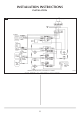
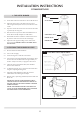
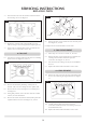
8.6 Remove the three screws and the fan motor from the panel.
See diagram 11, Arrow B.
8.7 Replace the fan and reassemble in reverse order.
9. FAN OVEN ELEMENT
9.1 Follow steps 11.1 and 11.2 in Section 11, Fan Unit.
9.2 Remove the three screws retaining the oven element and
carefully pull forward the element to expose the
connections. See diagram 11, Arrow C.
9.3 Disconnect the wires making sure they do not fall behind
the oven.
9.4 Replace the element and reassemble in reverse order.
10. GRILL ELEMENT
10.1 Remove the single screw from the rear of the element and
the two screws retaining the support bracket. See diagram
12.
12
AR1587
10.2 Carefully pull the element forward to expose the
connections and disconnect the wires making sure they do
not fall behind the oven.
10.3 Replace the element and reassemble in reverse order.
SERVICING INSTRUCTIONS
REPLACING PARTS
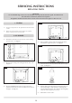
7.3 Disconnect the wires from the overheat switch and remove
the two fixing screws. See diagram 9.
9
AR1592
7.4 Replace the overheat switch and reassemble in reverse
order ensuring no wires are trapped when replacing the fan.
7.5 There is also an overheat switch on the conventional oven
element. To access this follow section 18.4
8. FAN UNIT
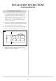
8.1 Open the top oven door and loosen the four screws holding
the fan cover. See diagram 10, Arrow A.
10
AR1557
8.2 Remove the thermostat phial lifting vertically from its
brackets. Take care not to damage the fine capillary tube.
8.3 Remove the four screws retaining the fan assembly panel.
See diagram 8.
8.4 Noting their positions, remove the wires from the overheat
switches, fan unit and element.
8.5 Remove the central nut (left-hand thread) and separate the
impellor from the fan motor. See diagram 11, Arrow A.