T3228-93110 (309) OWNER / OPERATOR MANUAL BRUSHCUTTERS BCZ2600S BCZ2600SU BCZ2600SW BCZ2600S BCZ2600SU BCZ2600SW WARNING WARNING The engine exhaust from this product contains chemicals known to the State of California to cause cancer, birth defects or other reproductive harm. Before using our brushcutters, please read this manual carefully to understand the proper use of your unit.
SAFETY FIRST Instructions contained in warnings within this manual marked with a symbol concern critical points which must be taken into consideration to prevent possible serious bodily injury, and for this reason you are requested to read all such instructions carefully and follow them without fail. ■ WARNINGS IN THE MANUAL WARNING This mark indicates instructions which must be followed in order to prevent accidents which could lead to serious bodily injury or death.
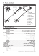
1. Parts location 16 BCZ2600S BCZ2600SU 6 3 5 15 14 BCZ2600SW 4 1 5 12 4 17 6 7 7 10 10 9 18 2 2 11 13 3 8 9 8 1. 2. 3. 4. 5. 6. 7. 8. 9. 10. 11. 12. 13. 14. 15. 16. 17. 18. Loop handle Shoulder strap hanger Ignition switch Throttle cable Throttle lever Throttle set button Drive shaft housing Debris guard Cutting line head Gear case Spark arrester Starter knob Fuel tank Primer pump Choke lever Air cleaner cover Handle Protector 2.
3. Warning labels on the machine (1) Read owner's manual before operating this machine. (2) Wear head, eye and ear protection. (3) Warning/Attention (4) Keep all children, bystanders and helpers 15 meters away from the brushcutter IMPORTANT If warning label peel off or become soiled and impossible to read, you should contact the dealer from which you purchased the product to order new labels and affix them in the required location(s). WARNING Never modify your brushcutter.
4. Symbols on the machine For safe operation and maintenance, symbols are carved in relief on the machine. According to these indications, please be careful not to take a mistake. (a) The port to refuel the "MIX GASOLINE" Position: FUEL TANK CAP (b) The direction to close the choke Position: AIR CLEANER COVER (c) The direction to open the choke Position: AIR CLEANER COVER IMPORTANT ENGINE INFORMATION THIS ENGINE MEETS U.S.
5. For safe operation 1. Read this manual carefully until you completely understand and follow all safety and operating instructions. 2. Keep this manual handy so that you may refer to it later whenever any questions arise. Also note, if you have any questions which cannot be answered herein, contact the dealer from whom you purchased the product. 3. Always be sure to include this manual when selling, lending, or otherwise transferring the ownership of this product. 4.
5. For safe operation b. At night, at times of heavy fog, or at any other times when your field of vision might be limited and it would be difficult to gain a clear view of the working area. c. During rain storms, during lightning storms, at times of strong or gale-force winds, or at any other times when weather conditions might make it unsafe to use the product. ■ WORKING PLAN 1.
5. For safe operation ■ BEFORE STARTING THE ENGINE 1. The area within a perimeter of 50 feet (15m) of the person using the product should be considered a hazardous area into which no one should enter. If necessary yellow warning rope, warning signs should be placed around the perimeter of the area.
5. For safe operation WARNING Never place the throttle into the high speed position when starting the engine. 3. After starting the engine, check to make sure that the cutting attachment stops rotating when the throttle is moved fully back to its original position. If it continues to rotate even after the throttle has been moved fully back, turn off the engine and take the unit to your authorized Red Max servicing dealer for repair.
5. For safe operation • IF SOMEONE COMES 1. Guard against hazardous situations at all times. Warn adults to keep pets and children away from the area. Be careful if you are approached. Injury may result from flying debris. 2. If someone calls out or otherwise interrupts you while working, always be sure to turn off the engine before turning around. ■ MAINTENANCE 1.
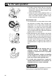
5. For safe operation refill the tank of the unit in any place where there is a boiler, stove, wood fire, electrical sparks, welding sparks, or any other source of heat or fire which might ignite the fuel. 2. Never smoke while operating the unit or refilling its fuel tank. 3. When refilling the tank, always turn off the engine and allow it to cool down. Take a careful look around to make sure that there are no sparks or open flames anywhere nearby before refueling. 4.
6. Set up (BCZ2600S, BCZ2600SU) ■ MOUNTING ENGINE (SE1) 1. Push the driveshaft housing toward the clutch housing and rotate it by hand to check that the driveshaft is engaged with the gears. 2. Insert the driveshaft housing into the clutch housing until it bottoms, and align the positioning holes on the clutch housing and the shaft tube and install the screw. When difficult to engage, twist the engine slightly. 3. Fasten the clamp securely with two screws.
6. Set up (BCZ2600SW) ■ MOUNTING ENGINE (SE5) 1. Push the driveshaft housing toward the clutch housing and rotate it by hand to check that the driveshaft is engaged with the gears. 2. Insert the driveshaft housing into the clutch housing until it bottoms, and align the positioning holes on the clutch housing and the shaft tube and install the screw. When difficult to engage, twist the engine slightly. 3. Fasten the clamp securely with two screws. SE5 SE6 IMPORTANT Tighten the screws gradually by turns.
6. Set up SE10 SE11 ■ INSTALLING CUTTING HEAD (SE10) 1. While locking the gear shaft, by inserting the supplied tool into the upper holder on the gear box, loosen and remove the hexagon nut(lefthanded) 2. Fit the holder attached to the upper holder. Then screw in the cutting head to the gear shaft over the holders. Hand-tighten it securely. ■ BALANCE UNIT 1. Put on strap and attach unit to strap. 2. Slide clamp up or down until unit balances with head just touching on the ground.
7. Fuel WARNING • Gasoline is very flammable. Avoid smoking or bringing any flame or sparks near fuel. Make sure to stop the engine and allow it cool before refueling the unit. Select outdoor bare ground for fueling and move at least 3m (10ft) away from the fueling point before starting the engine. • The RedMax engines are lubricated by oil specially formulated for air-cooled 2-cycle gasoline engine use.
7. Fuel again for at least one minute. As some oils may be difficult to agitate depending on oil ingredients, sufficient agitation is necessary for the engine to last long. Be careful that, if the agitation is insufficient, there is an increased danger of early piston seizing due to abnormally lean mixture. 5. Put a clear indication on the outside of the container to avoid mixing up with gasoline or other containers. 6. Indicate the contents on outside of container for easy identification.
8. Operation ■ STARTING ENGINE OP1 WARNING The cutting head will start rotating upon the engine starts. OP2 (1) (2) (3) OP3 (5) 1. Rest the unit on a flat, firm place. Keep the cutting head off the ground and clear of surrounding objects as it will start rotating upon starting of the engine. 2. Push the primer pump several times until overflown fuel flows out in the clear tube. (OP1) 3. Move the choke lever to the closed position. (OP2) 4. Set the ignition switch to the “start” position.
8. Operation ■ STOPPING ENGINE (OP3) 1. Release the throttle lever and run the engine for a half minute. 2. Shift the ignition switch to the STOP position. IMPORTANT • Except for an emergency, avoid stopping the engine while pulling the throttle lever. OP5 ■ ADJUSTING THROTTLE CABLE • The normal play is 1 or 2mm when measured at the carburetor side end. Readjust with the cable adjuster as required. (OP5) .04 in (1~2mm) (1) (1) cable adjuster ■ ADJUSTING IDLING SPEED (OP6) 1.
8. Operation crowding the line into the cutting area. Allow the unit to trim at its own pace. OP7 1. Hold the unit so the head is off the ground and is tilted about 20 degrees toward the sweep direction. (OP7) 2. You can avoid thrown debris by sweeping from your left to the right. 3. Use a slow, deliberate action to cut heavy growth. The rate of cutting motion will depend on the material being cut. Heavy growth will require slower action than will light growth. 4.
9. Maintenance ■ MAINTENANCE CHART E N G I N E S H A F T every every every 25 50 100 system/compornent procedure before hours hours hours note use after after after fuel leaks, fuel spillage wipe out ✔ fuel tank, air filter, fuel filter inspect/clean ✔ ✔ replace, if necessary see ■ADJUSTING replace carburetor idle adjusting screw ✔ IDLING SPEED (p.19) if necessary clean and readjust GAP: .025in(0.6~0.
9. Maintenance WARNING • Make sure that the engine has stopped and is cool before performing any service to the machine. Contact with moving cutting head or hot muffler may result in a personal injury. MA2 ■ AIR FILTER • The air filter, if clogged, will reduce the engine performance. Check and clean the filter element in warm, soapy water as required. Dry completely before installing. If the element is broken or shrunk, replace with a new one.
9. Maintenance ■ MUFFLER WARNING • Inspect periodically, the muffler for loose fasteners, any damage or corrosion. If any sign of exhaust leakage is found, stop using the machine and have it repaired immediately. • Note that failing to do so may result in the engine catching on fire. MA5 (1) ■ SPARK ARRESTER • The muffler is equipped with a spark arrester to prevent red hot carbon from flying out of the exhaust outlet. Periodically inspect and clean as necessary with a wire brush.
9. Maintenance MA7 (1) (2) themselves to the brushcutter. Failing to do so could cause the muffler to become overheated, and that this in turn could cause the engine to catch on fire. Always make sure that the muffler is clean and free of wood chips, leaves, and other waste before use. • Check the intake air cooling vent and the area around the cylinder cooling fins after every 25 hours of use for blockage, and remove any waste which has attached itself to the brushcutter.
10. Storage • Aged fuel is one of major causes of engine starting failure. Before storing the unit, empty the fuel tank and run the engine until it uses all the fuel left in the fuel line and the carburetor. Store the unit indoor taking necessary measures for rust prevention.
11. Optional blade usage OPT1 9” 22-tooth: SST229 9” 24-tooth: SST249 CUTTER APPLICATION CHART 8” 8-tooth: SGB088 9” 8-tooth: SGB089 8” 4-tooth: SGB048 9” 4-tooth: SGB049 Nylon line head Under growth Heavy weeds Light weeds Grass ■ CHOOSE THE BLADE Choose a suitable recommended cutting attachment according to the object to be cut. (OPT1) • When replacing blade always be sure to use products which have been certified by RedMax.
11. Optional blade usage IMPORTANT OPT3 BCZ2600S BCZ2600SU [ BCZ2600S, BCZ2600SU ] Change to the debris guard which is suitable for the metal blade. (OPT3) TIGHTENING TORQUE: (1)Guard Ass’y: (2)Guard: (3)Plate Comp.: (4)Plate: (5)Blade: OPT4 BCZ2600S BCZ2600SU 6489-24000 6489-24110 6489-24200 6489-24210 6489-24220 130~174 in-lbs (14.7~19.6 N.m.
11. Optional blade usage speed is too low, or the blade cuts too deep into weeds. Adjust the engine speed and cutting depth according to the condition of object. WARNING • If the grass or other object gets caught in the blade, or if the unit starts to shake or vibrate, turn off the engine and check the whole unit. Change the blade if it has been damaged. • Turn off the engine and make sure the blade has completely stop before checking the blade, and removing any object got caught in. OPT7 ■ OPERATION 1.
11. Optional blade usage you understand what causes kick out, how you can reduce the chance of kick out and how you can remain in control of the unit if kick out does occur. 1. What causes kick out: • Kick out can occur when the moving blade contacts an object that it cannot cut. This contact causes the blade to stop for an instant and then suddenly move or ”bounce” away from the object that was hit.
11. Optional blade usage OPT9 ■ MAINTENANCE BLADE • Check the blade and the fasteners for looseness, cracking, or bending. • Check the cutting edges and reform with a flat file. Point (OPT9) : 1. Keep the end corner sharp. 2. Round the root of the edge, using round file. 3. Do not use water when using a grinder. IMPORTANT • It is recommended that filing should be done by professionals. • Especially regarding filing the saw blade, Leave it to the professionals.
12. Troubleshooting guide Case 1. Starting failure CHECK fuel tank fuel filter carburetor adjustment screw sparking (no spark) spark plug ➞ ➞ ➞ ➞ ➞ ➞ PROBABLE CAUSES incorrect fuel fuel filter is clogged out of normal range spark plug is fouled/wet plug gap is incorrect disconnected ➞ ➞ ➞ ➞ ➞ ➞ ACTION drain it and with correct fuel clean adjust to normal range clean/dry correct (GAP: 0.6~0.7mm) retighten Case 2. Engine starts but does not keep running/Hard re-starting.
32
13. Parts list BRUSHCUTTERS BCZ2600S BCZ2600SU BCZ2600SW NOTE : 1. Use KOMATSU ZENOAH genuine parts as specified in the parts list for repair and/or replacement. 2. KOMATSU ZENOAH does not warrant the machines, which have been damaged by the use of any parts other than those specified by the company. 3.
13. Parts list Fig.
BCZ2600S (S/N 300001 and up) Fig.1 DRIVE UNIT BCZ2600SU (S/N 300001 and up) Key# 1A* 1B* 2 3 4 5 6 7 8 9 10 11 12 13 14 15 16 17 18 19 20 21 22 23 24 25 26 27 28 29 30 31 32 33 34 35 36 37 38 39A* 39B* Description PIPE-COMP, 1500xø24xT1.7 PIPE-COMP, 1500xø24xT1.
13. Parts list Fig.
Fig.2 DRIVE UNIT BCZ2600SW (S/N 300001 and up) Key# Description 1 2 3 4 5 6 7 8 9 10 11 12 13 14 15 16 17 18 19 20 21 22 23 24 25 26 27 28 PIPE-COMP, 1500xø24xT1.
13. Parts list Fig.
BCZ2600S (S/N 300101 and up) BCZ2600SU (S/N 300101 and up) Fig.
CALIFORNIA EMISSION CONTROL WARRANTY STATEMENT YOUR WARRANTY RIGHTS AND OBLIGATIONS The California Air Resources Board and KOMATSU ZENOAH are pleased to explain the emission control system warranty on your 1995 and later small off-road engine. In California, new small off-road engines must be designed, built and equipped to meet the state’s stringent anti-smog standards.
RedMax 2-YEAR LIMITED WARRANTY EMISSION-RELATED PARTS, FOR TWO (2) YEARS FROM THE DATE OF ORIGINAL DELIVERY, KOMATSU ZENOAH AMERICA INC. (THE COMPANY), THROUGH ANY RedMax DEALER, WILL REPAIR OR REPLACE, FREE OF CHARGE, FOR THE ORIGINAL AND EACH SUBSEQUENT PURCHASER, ANY PART OR PARTS FOUND TO BE DEFECTIVE IN MATERIAL AND/OR WORKMANSHIP.
RedMax Garantie limitée à 2 ans Pièces en rapport avec les émissions de gaz d'échappement : KOMATSU ZENOAH AMERICA INC., par l'intermédiaire de n'importe quel revendeur RedMax, réparera gratuitement ou remplacera gratuitement pour l'acheteur initial et chaque acheteur successif toute(s) pièce(s) se révélant de constitution et/ou de montage défectueux pendant deux (2) ans à compter de la date initiale de livraison d’une unité.
KOMATSU ZENOAH AMERICA INC. 4344 Shackleford Road Suite 500 Norcross, Georgia 30093 © Printed in U.S.A.