T1503-93110(912) OWNER / OPERATOR MANUAL LONG REACH TRIMMER LRTZ2500 WARNING WARNING The engine exhaust from this product contains chemicals known to the State of California to cause cancer, birth defects or other reproductive harm. Before using our trimmers, please read this manual carefully to understand the proper use of your unit.
INFORMATION This machine is equipped with an Overload Cancellation Mechanism. When the cutting blades have got into metal wires or those twigs difficult to cut, the mechanism acts as a shock absorber, and protects the drive gears and the blades from severe reaction which could give damage to those parts. When the blades are frequently caught by twigs, please check the following points: 1. Size of the twigs. NEVER TRY TO CUT TWIGS THICKER THAN 3/16” (5mm). 2. Condition of the blade edges.
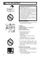
SAFETY FIRST Instructions contained in warnings within this manual marked with a symbol concern critical points which must be taken into consideration to prevent possible serious bodily injury, and for this reason you are requested to read all such instructions carefully and follow them without fail. ■ WARNINGS IN THE MANUAL WARNING This mark indicates instructions which must be followed in order to prevent accidents which could lead to serious bodily injury or death.
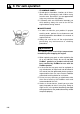
1. Parts location 1. 2. 3. 4. 5. 6. 7. 8. Loop handle Shoulder strap hanger Ignition switch Throttle cable Throttle lever Throttle set button Drive shaft housing Blade 9. 10. 11. 12. 13. 14. 15. Gear case Spark arrester Starter knob Fuel tank Primer pump Choke lever Air cleaner cover 2. Specifications ■ LRTZ2500 Overall size(LxWxH)························································ 90.1(2300)x9.8(250)x12.2(310) in(mm) Dry weight w/o acc.
3. Warning labels on the machine (1) Read owner's manual before operating this machine. (2) Wear head, eye and ear protection. (3) Handling this machine improperly could result in accidents causing serious injury or death. Read this manual carefully and practice using the trimmer until you are fully acquainted with all operations and have learned to use it correctly.
5. For safe operation 1. Read this manual carefully until you completely understand and follow all safety and operating instructions. 2. Keep this manual handy so that you may refer to it later whenever any questions arise. Also note, if you have any questions which cannot be answered herein, contact the dealer from whom you purchased the product. 3. Always be sure to include this manual when selling, lending, or otherwise transferring the ownership of this product. 4.
5. For safe operation b. At night, at times of heavy fog, or at any other times when your field of vision might be limited and it would be difficult to gain a clear view of the working area. c. During rain storms, during lightning storms, at times of strong or gale-force winds, or at any other times when weather conditions might make it unsafe to use the product. ■ WORKING PLAN 1.
5. For safe operation ■ BEFORE STARTING THE ENGINE 1. The area within a perimeter of 50 feet (15m) of the person using the product should be considered a hazardous area into which no one should enter. If necessary yellow warning rope, warning signs should be placed around the perimeter of the area.
5. For safe operation WARNING Never place the throttle into the high speed position when starting the engine. 3. After starting the engine, check to make sure that the cutting attachment stops rotating when the throttle is moved fully back to its original position. If it continues to rotate even after the throttle has been moved fully back, turn off the engine and take the unit to your authorized Red Max servicing dealer for repair.
5. For safe operation • IF SOMEONE COMES 1. Guard against hazardous situations at all times. Warn adults to keep pets and children away from the area. Be careful if you are approached. Injury may result from flying debris. 2. If someone calls out or otherwise interrupts you while working, always be sure to turn off the engine before turning around. ■ MAINTENANCE 1.
5. For safe operation ■ HANDLING FUEL 1. The engine of the RedMax product is designed to run on a mixed fuel which contains highly flammable gasoline. Never store cans of fuel or refill the tank of the unit in any place where there is a boiler, stove, wood fire, electrical sparks, welding sparks, or any other source of heat or fire which might ignite the fuel. 2. Never smoke while operating the unit or refilling its fuel tank. 3. When refilling the tank, always turn off the engine and allow it to cool down.
6. Set up ■ MOUNTING ENGINE (SE1) 1. Push the driveshaft housing toward the clutch housing and rotate it by hand to check that the driveshaft is engaged with the gears. 2. Insert the driveshaft housing into the clutch housing until it bottoms, and align the positioning holes on the clutch housing and the shaft tube and install the screw. When difficult to engage, twist the engine slightly. 3. Fasten the clamp securely with two screws. SE1 SE2 IMPORTANT Tighten the screws gradually by turns.
6. Set up SE4 ■ ATTACHING THE TRIMMING MECHANISM (SE4) 1. Remove the cap on the end of the main pipe. 2. Remove the screw screwed into the end of the trimming mechanism. 3. Insert the end of the trimming mechanism into the main pipe. 4. Line up the hole on the end of the trimming mechanism into which the screw is to be inserted with the hole on the main pipe, and screw the screw firmly in. 5. Using a 10-mm wrench, screw in the hexagonal bolt provided to fix the trimming mechanism into place.
7. Fuel WARNING • Gasoline is very flammable. Avoid smoking or bringing any flame or sparks near fuel. Make sure to stop the engine and allow it cool before refueling the unit. Select outdoor bare ground for fueling and move at least 3m(10ft) away from the fueling point before starting the engine. • The RedMax engines are lubricated by oil specially formulated for air-cooled 2-cycle gasoline engine use.
7. Fuel container to avoid mixing up with gasoline or other containers. 6. Indicate the contents on outside of container for easy identification. ■ FUELING THE UNIT 1. Untwist and remove the fuel cap. Rest the cap on a dustless place. 2. Put fuel into the fuel tank to 80% of the full capacity. 3. Fasten the fuel cap securely and wipe up any fuel spillage around the unit. WARNING 1. Select bare ground for fueling. 2. Move at least 10 feet (3 meters) away from the fueling point before starting the engine. 3.
8. Operation ■ STARTING ENGINE OP1 WARNING The cutting head will start rotating upon the engine starts. OP2 (1) (2) (3) OP3 (5) (6) (4) 1. Rest the unit on a flat, firm place. Keep the cutting head off the ground and clear of surrounding objects as it will start rotating upon starting of the engine. 2. Push the primer pump several times until overflown fuel flows out in the clear tube. (OP1) 3. Move the choke lever to the closed position. (OP2) 4. Set the ignition switch to the “start” position.
8. Operation ■ STOPPING ENGINE (OP3) 1. Release the throttle lever and run the engine for a half minute. 2. Shift the ignition switch to the STOP position. IMPORTANT • Except for an emergency, avoid stopping the engine while pulling the throttle lever. ■ ADJUSTING THROTTLE CABLE • The normal play is 1 or 2mm when measured at the carburetor side end. Readjust with the cable adjuster as required. (OP5) (1) cable adjuster OP5 .04 in (1~2mm) (1) OP6 ■ ADJUSTING IDLING SPEED (OP6) 1.
8. Operation is in operation. • Always be sure to turn off the engine before changing the angle of the blades, removing branches which have become stuck in the blades, or at any other time when coming into close proximity with the blades. • Always wear work gloves made of leather or some other sturdy material when using the trimmer. • Always place the blade cover provided with the trimmer over the blades when not in use.
9. Maintenance SHAFT ENGINE ■ MAINTENANCE CHART every every every 25 50 100 system/compornent procedure before hours hours hours note use after after after fuel leaks, fuel spillage wipe out ✔ fuel tank, air filter, fuel filter inspect/clean ✔ ✔ replace, if necessary see ■ADJUSTING replace carburetor idle adjusting screw ✔ IDLING SPEED (p.17) if necessary clean and readjust GAP: .025in(0.6~0.
9. Maintenance QUICK TIP If the blades become so worn down that it is no longer possible to eliminate the gap between them, you should contact the authorized RedMax servicing dealer from which you purchased your RedMax® trimmer to have the blades resharpened or replaced. ■ GEAR CASE The reduction gears are lubricated by multipurpose, lithium-based grease in the gearcase. Supply new grease every 25 hours of use or more often depending on the job condition.
9. Maintenance ■ SPARK PLUG • Starting failure and mis-firing are often caused by a fouled spark plug. Clean the spark plug and check that the plug gap is in the correct range. For a replacement plug, use the correct type specified by RedMax. (MA5) • REPLACEMENT PLUG IS A NGK CMR7A. MA5 IMPORTANT .025 in 0.655mm • Note that using any spark plug other than those designated may result in the engine failing to operate properly or in the engine becoming overheated and damaged.
9. Maintenance ■ INTAKE AIR COOLING VENT WARNING • Never touch the cylinder, muffler, or spark plugs with your bare hands immediately after stopping the engine. The engine can become very hot when in operation, and doing so could result in severe burns. • When checking the machine to make sure that it is okay before using it, check the area around the muffler and remove any wood chips or leaves which have attached themselves to the trimmer.
10. Storage • Aged fuel is one of major causes of engine starting failure. Before storing the unit, empty the fuel tank and run the engine until it uses all the fuel left in the fuel line and the carburetor. Store the unit indoor taking necessary measures for rust prevention.
11. Troubleshooting guide Case 1. Starting failure CHECK fuel tank fuel filter carburetor adjustment screw sparking (no spark) spark plug ➞ ➞ ➞ ➞ ➞ ➞ PROBABLE CAUSES incorrect fuel fuel filter is clogged out of normal range spark plug is fouled/wet plug gap is incorrect disconnected ➞ ➞ ➞ ➞ ➞ ➞ ACTION drain it and with correct fuel clean adjust to normal range clean/dry correct (GAP: 0.6~0.7mm) retighten Case 2. Engine starts but does not keep running/Hard re-starting.
12. Parts list LONG REACH TRIMMER LRTZ2500 NOTE : 1. Use KOMATSU ZENOAH genuine parts as specified in the parts list for repair and/or replacement. 2. KOMATSU ZENOAH does not warrant the machines, which have been damaged by the use of any parts other than those specified by the company. 3. When placing parts orders for repair and/or replacement, check if the model name and the serial number are applicable to those specified in the parts list, then use parts number described in the parts list. 4.
12. Parts list Fig.1 DRIVE UNIT LRTZ2500 (S/N 000000 and up) Fig.
Fig.
12. Parts list Fig.
Fig.
CALIFORNIA EMISSION CONTROL WARRANTY STATEMENT YOUR WARRANTY RIGHTS AND OBLIGATIONS The California Air Resources Board and KOMATSU ZENOAH are pleased to explain the emission control system warranty on your 1995 and later small off-road engine. In California, new small off-road engines must be designed, built and equipped to meet the state’s stringent anti-smog standards.
Red Max TRIMMER MODEL LRTZ2500 2-YEAR LIMITED WARRANTY EMISSION-RELATED PARTS, FOR TWO (2) YEARS FROM THE DATE OF ORIGINAL DELIVERY OF THE MODEL LRTZ2500, UNIT, KOMATSU ZENOAH AMERICA INC. (THE COMPANY), THROUGH ANY RedMax DEALER, WILL REPAIR OR REPLACE, FREE OF CHARGE, FOR THE ORIGINAL AND EACH SUBSEQUENT PURCHASER, ANY PART OR PARTS FOUND TO BE DEFECTIVE IN MATERIAL AND/OR WORKMANSHIP.
KOMATSU ZENOAH AMERICA INC.