T3066-93110(103) OWNER / OPERATOR MANUAL RECIPROCATOR SGCZ2500S WARNING WARNING The engine exhaust from this product contains chemicals known to the State of California to cause cancer, birth defects or other reproductive harm. Before using our products, please read this manual carefully to understand the proper use of your unit.
SAFETY FIRST Instructions contained in warnings within this manual marked with a symbol concern critical points which must be taken into consideration to prevent possible serious bodily injury, and for this reason you are requested to read all such instructions carefully and follow them without fail. ■ WARNINGS IN THE MANUAL WARNING This mark indicates instructions which must be followed in order to prevent accidents which could lead to serious bodily injury or death.
1. Parts location 1. 2. 3. 4. 5. 6. 7. 8. Loop handle Shoulder strap hanger Ignition switch Throttle cable Throttle lever Throttle set button Drive shaft housing Debris guard 9. 10. 11. 12. 13. 14. 15. 16. Blade Cuttercase Spark arrester Starter knob Fuel tank Primer pump Choke lever Air cleaner cover 2. Specifications ■ SGCZ2500S Overall size(LxWxH)·························································· 76.0(1930)x9.8(250)x9.8(250) in(mm) Dry weight w/o acc.
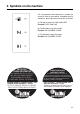
3. Symbols on the machine For safe operation and maintenance, symbols are carved in relief on the machine. According to these indications, please be careful not to take a mistake. (a) The port to refuel the "MIX GASOLINE" Position: FUEL TANK CAP (b) The direction to close the choke Position: AIR CLEANER COVER (c) The direction to open the choke Position: AIR CLEANER COVER IMPORTANT ENGINE INFORMATION THIS ENGINE MEETS U.S.
4. For safe operation 1. Read this manual carefully until you completely understand and follow all safety and operating instructions. 2. Keep this manual handy so that you may refer to it later whenever any questions arise. Also note, if you have any questions which cannot be answered herein, contact the dealer from whom you purchased the product. 3. Always be sure to include this manual when selling, lending, or otherwise transferring the ownership of this product. 4.
4. For safe operation b. At night, at times of heavy fog, or at any other times when your field of vision might be limited and it would be difficult to gain a clear view of the working area. c. During rain storms, during lightning storms, at times of strong or gale-force winds, or at any other times when weather conditions might make it unsafe to use the product. ■ WORKING PLAN 1.
4. For safe operation ■ BEFORE STARTING THE ENGINE 1. The area within a perimeter of 50 feet (15m) of the person using the product should be considered a hazardous area into which no one should enter. If necessary yellow warning rope, warning signs should be placed around the perimeter of the area.
4. For safe operation WARNING Never place the throttle into the high speed position when starting the engine. 2. After starting the engine, check to make sure that the cutting attachment stops rotating when the throttle is moved fully back to its original position. If it continues to rotate even after the throttle has been moved fully back, turn off the engine and take the unit to your authorized Red Max servicing dealer for repair.
4. For safe operation • IF SOMEONE COMES 1. Guard against hazardous situations at all times. Warn adults to keep pets and children away from the area. Be careful if you are approached. Injury may result from flying debris. 2. If someone calls out or otherwise interrupts you while working, always be sure to turn off the engine before turning around. ■ MAINTENANCE 1.
4. For safe operation refill the tank of the unit in any place where there is a boiler, stove, wood fire, electrical sparks, welding sparks, or any other source of heat or fire which might ignite the fuel. 2. Never smoke while operating the unit or refilling its fuel tank. 3. When refilling the tank, always turn off the engine and allow it to cool down. Take a careful look around to make sure that there are no sparks or open flames anywhere nearby before refueling. 4.
5. Set up SE1 ■ MOUNTING ENGINE (SE1) 1. Install the engine to the driveshaft so that the cylinder head and the stop switch may come on the same side. 2. Using attached four bolts, secure the connection firmly with equal force (Torque: 25in-lbs)(Torque: 2.8 N.m.). (1) Bolt (2) Stop switch WARNING Never use any screws other than those specified by the manufacturer, or the engine can get loose, resulting in a hazardous event. IMPORTANT Tighten the screws gradually by turns.
5. Set up ■ BLADE CUTTERCASE (SE4) WARNING The blade has very sharp edges. Be sure to use protective gloves whenever handling it. SE4 1. Remove the fastening screw (long) and the lock screw (short) from the cuttercase. 2. While aligning the locking holes (cuttercase hole, spacer hole, and shaft casing hole) install the cuttercase assembly to the shaft casing. If it will not bottom, twist the case slightly back and forth. 3.
6. Fuel WARNING • Gasoline is very flammable. Avoid smoking or bringing any flame or sparks near fuel. Make sure to stop the engine and allow it cool before refueling the unit. Select outdoor bare ground for fueling and move at least 3m(10ft) away from the fueling point before starting the engine. • The RedMax engines are lubricated by oil specially formulated for air-cooled 2-cycle gasoline engine use.
6. Fuel container to avoid mixing up with gasoline or other containers. 6. Indicate the contents on outside of container for easy identification. ■ FUELING THE UNIT 1. Untwist and remove the fuel cap. Rest the cap on a dustless place. 2. Put fuel into the fuel tank to 80% of the full capacity. 3. Fasten the fuel cap securely and wipe up any fuel spillage around the unit. WARNING 1. Select bare ground for fueling. 2. Move at least 10 feet (3 meters) away from the fueling point before starting the engine. 3.
7. Operation ■ STARTING ENGINE OP1 WARNING The cutting head will start rotating upon the engine starts. OP2 (1) (2) (3) 1. Rest the unit on a flat, firm place. Keep the cutting head off the ground and clear of surrounding objects as it will start rotating upon starting of the engine. 2. Push the primer pump several times until overflown fuel flows out in the clear tube. (OP1) 3. Move the choke lever to the closed position. (OP2) 4. Set the ignition switch to the “start” position. (OP3) 5.
7. Operation engine while pulling the throttle lever. OP5 .04 in (1~2mm) ■ ADJUSTING THROTTLE CABLE • The normal play is 1 or 2mm when measured at the carburetor side end. Readjust with the cable adjuster as required. (OP5) (1) cable adjuster (1) OP6 ■ ADJUSTING IDLING SPEED (OP6) 1. When the engine tends stop frequently at idling mode, turn the adjusting screw clockwise. 2. When the cutting head keeps rotating after releasing the trigger, turn the adjusting screw counter-clockwise.
7. Operation Parking area machine control. 3. Since the blade does not cause cut grass to wrap around the neck, you need not to stop operation to remove such wrappers. Among trees What's more, since the whole circle of the blade is available for cutting, you can move the cutting head in all directions and cut grass growing on such place difficult-to-get with conventional trimmer. You can even trim the waterside without splashing water.
8. Maintenance ■ MAINTENANCE CHART E N G I N E S H A F T every every every 25 50 100 system/compornent procedure before hours hours hours note use after after after fuel leaks, fuel spillage wipe out ✔ fuel tank, air filter, fuel filter inspect/clean ✔ ✔ replace, if necessary see ■ADJUSTING replace carburetor idle adjusting screw ✔ IDLING SPEED (p.17) if necessary clean and readjust GAP: .025in(0.6~0.
8. Maintenance MA2 To Sharpen Blade: 1. When the corners of cutter become rounded and the cutting edges become dull, resharpen using a small disk grinder, etc. (MA2) 2. When sharpening, offset the top and bottom blade teeth by 1/8 inches (3.125mm), as shown in the illustration. (MA3) (1) Offset (2) Top blade (3) Bottom blade MA3 NOTE Apply the grinder lightly and quickly. Pressing too strongly or grinding for too long will generate heat which can soften the temper of the blade and accelerate wear.
8. Maintenance WARNING • Make sure that the engine has stopped and is cool before performing any service to the machine. Contact with moving cutting head or hot muffler may result in a personal injury. MA6 (1) MA7 ■ AIR FILTER • The air filter, if clogged, will reduce the engine performance. Check and clean the filter element in warm, soapy water as required. Dry completely before installing. If the element is broken or shrunk, replace with a new one.
8. Maintenance machine and have it repaired immediately. • Note that failing to do so may result in the engine catching on fire. MA9 (1) MA10 ■ SPARK ARRESTER • The muffler is equipped with a spark arrester to prevent red hot carbon from flying out of the exhaust outlet. Periodically inspect and clean as necessary with a wire brush.
8. Maintenance MA11 (1) around the cylinder cooling fins after every 25 hours of use for blockage, and remove any waste which has attached itself to the reciprocator. Note that it is necessary to remove the engine cover shown in (MA11) in order to be able to view the upper part of the cylinder.
10. Troubleshooting guide Case 1. Starting failure CHECK fuel tank fuel filter carburetor adjustment screw sparking (no spark) spark plug ➞ ➞ ➞ ➞ ➞ ➞ PROBABLE CAUSES incorrect fuel fuel filter is clogged out of normal range spark plug is fouled/wet plug gap is incorrect disconnected ➞ ➞ ➞ ➞ ➞ ➞ ACTION drain it and with correct fuel clean adjust to normal range clean/dry correct (GAP: 0.6~0.7mm) retighten Case 2. Engine starts but does not keep running/Hard re-starting.
11. Parts list RECIPROCATOR SGCZ2500S NOTE : 1. Use KOMATSU ZENOAH genuine parts as specified in the parts list for repair and/or replacement. 2. KOMATSU ZENOAH does not warrant the machines, which have been damaged by the use of any parts other than those specified by the company. 3. When placing parts orders for repair and/or replacement, check if the model name and the serial number are applicable to those specified in the parts list, then use parts number described in the parts list. 4.
11. Parts list Fig.1 DRIVE UNIT (S/N: 000101 and up) Fig.
Fig.
11. Parts list Fig.
Fig.
CALIFORNIA EMISSION CONTROL WARRANTY STATEMENT YOUR WARRANTY RIGHTS AND OBLIGATIONS The California Air Resources Board and KOMATSU ZENOAH are pleased to explain the emission control system warranty on your 1995 and later small off-road engine. In California, new small off-road engines must be designed, built and equipped to meet the state’s stringent anti-smog standards.
RedMax 2-YEAR LIMITED WARRANTY EMISSION-RELATED PARTS, FOR TWO (2) YEARS FROM THE DATE OF ORIGINAL DELIVERY, KOMATSU ZENOAH AMERICA INC. (THE COMPANY), THROUGH ANY RedMax DEALER, WILL REPAIR OR REPLACE, FREE OF CHARGE, FOR THE ORIGINAL AND EACH SUBSEQUENT PURCHASER, ANY PART OR PARTS FOUND TO BE DEFECTIVE IN MATERIAL AND/OR WORKMANSHIP.
RedMax Garantie limitée à 2 ans Pièces en rapport avec les émissions de gaz d'échappement : KOMATSU ZENOAH AMERICA INC., par l'intermédiaire de n'importe quel revendeur RedMax, réparera gratuitement ou remplacera gratuitement pour l'acheteur initial et chaque acheteur successif toute(s) pièce(s) se révélant de constitution et/ou de montage défectueux pendant deux (2) ans à compter de la date initiale de livraison d’une unité.