
User guide


Redpine Signals, Inc. Proprietary and Confidential. Page 103
R
R
S
S
9
9
1
1
1
1
0
0
-
-
N
N
-
-
1
1
1
1
-
-
2
2
2
2
/
/
2
2
4
4
/
/
2
2
8
8
S
S
o
o
f
f
t
t
w
w
a
a
r
r
e
e
P
P
r
r
o
o
g
g
r
r
a
a
m
m
m
m
i
i
n
n
g
g
R
R
e
e
f
f
e
e
r
r
e
e
n
n
c
c
e
e
M
M
a
a
n
n
u
u
a
a
l
l
V
V
e
e
r
r
s
s
i
i
o
o
n
n
4
4
.
.
1
1
5
5
Padded data <W0[7:0]> <W1[7:0]> <W2[7:0]> <W3[7:0]> <W4[7:0]>
<D5[7:0]><D6[7:0]><D7[7:0]> , where D[7:0] is the dummy data.
The first byte sent is W0, the second byte sent is W1 and so on (refer Bit
ordering of SPI transmission/reception).
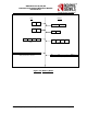
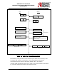
4.5.2 Frame Write (Slave Write)
The sequence of command transactions (with no failure from the slave) for a
Frame Write (also called slave write) is as described in the figure below. The
operations are similar to the memory write – except that bit 3 of C1 is set and
the Address phase (A0,A1, A2, A3) is skipped.
Figure 21: Frame Write using SPI Commands
The following is the procedure to be followed by the Host.
1. Prepare and send the commands C1, C2 together as described for Slave
write.
2. Read the response (R) from the SPI slave (RS9110-N-11-2X module).
3. Status 0x58 indicates that the slave is ready. Host can send the commands
C3 and C4, followed by the data. Status 0x54 indicates that the device is busy.
Host has to retry. Status equal to 0x 52 indicates a failure response.
Data payload size should be in multiples of 4 bytes in this operation. For
example, if 5 bytes of data is to be written, it should be padded with 3 more
dummy bytes to make it 8 bytes (multiple of 4) before sending.
Host
Module
C1
C2
C3
C4
Dummy
R (0x58)
R
R
W0
W1
W(N-1)
……
….
D0
D1
D(N-1)
……
….
Dummy Response
Data payload to be written