
User Manual


Redpine Signals, Inc. Page 9
Connect
-
io
-
n™
RS9110-N-11-24
Evaluation Board User Guide
V
V
e
e
r
r
s
s
i
i
o
o
n
n
3
3
.
.
1
1
3
3
sourcing capacity of the
Host should be 500mA.
If not used, this pin
should be left open
5
SPI_CLK
Input
SPI clock
6
GND
-
Ground
7
SPI_MOSI
Input
SPI data input
8
SPI_MISO
Output
SPI data output
9
INTR
Output
Interrupt output (Active
high)
10
NC
-
No connect
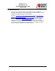
Table 2: SPI Header Pins
DIP Switches
The DIP switches are used to select the module to work in UART or SPI mode.
Switch
#
Status
Comment
1,2,3
ON, OFF, OFF
Power on reset selected
1,2,3
OFF, ON, OFF
Push button reset
selected
1,2,3
OFF, OFF, ON
Reset from Host
selected
4,5
ON, ON
SPI mode selected
4,5
OFF, OFF
UART mode selected
6
OFF
Keep in OFF mode
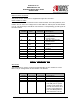
Table 3: DIP Switch Setting (6 switches)
Note: If Reset from Host selected using DIP switch settings then 14
th
pin of GPIO
header should be connected to the host. If EVB has 4 switches DIP switch then
resistor R19 should be populated with 0 ohms.
SW4 and SW5
These switches are used to select the UART DB9 connector or the “UART Header
for MCU” for communicating using the UART interface. The direction shown with
the thick red arrow is to select the DB9 connector. The direction shown with the
thick black arrow is to select the UART Header.
2 Pin Jumper
Used for Power measurements.